I spent a few hrs last night ripping apart my old pc power supplies, laptop chargers, broken xbox boards, and broken subwoofer amps. Ended up finding a ton of mosfets, which I then had some learning to do.. The only problem is most of them need a 20 volt current to turn on. Could I bypass this issue with a capacitor? Or would the mosfet just turn off immediately after the initial burst?From what information I found on that MOSFET, it won't work. To high a resistance and too high a turn on voltage for box mods.
Become a Patron!
You are using an out of date browser. It may not display this or other websites correctly.
You should upgrade or use an alternative browser.
You should upgrade or use an alternative browser.
Basic MOSFET wiring
- Thread starter Vape_geek
- Start date
DIY FancyLights
Member For 4 Years
The MOSFET's need a certain voltage on the gate to turn them on and keep them on, which is why the preferred parts a usually called Logic or sub-Logic Level so they turn on below 3V. Standard MOSFET's like you find in many power supplies need > 10V to turn on. On spec sheets, the voltage they start to turn on at is listed as Vgs(thr), but you also need to watch what the Rds(on) is at the voltage you will be using, because that resistance can cause problems with things like box mods.
So i managed to find a MOSFET made by STELECTRONICS, its a "60N55F3" its a TO-220FP.. VGS(th): 2 - 4V, and RDS(on): 6.5 - 8.5 mΩ, Would this be a reliable mosfet to use in a Series build?
DIY FancyLights
Member For 4 Years
Most moders like to have 2,Ohm or less so the MOSFET doesn't get too warm because of the limited cooling. The currently recommended MOSFET's I've seen include IRLB3034PBF, IRLB3813PBF, PSMN1R9-40PLQ, and the newest addition of the PSMN0R9-25 (surface mount) which is what I use on the 'microFET' board I sell on eBay which also include the pulldown resistor and very easy to install.
An early one people liked but have been moving away from more is the IRLB8743PBF, but in a series build this is still a possibility, just not as good for parallels as the others.
An early one people liked but have been moving away from more is the IRLB8743PBF, but in a series build this is still a possibility, just not as good for parallels as the others.
http://pdf1.alldatasheet.com/datasheet-pdf/view/37892/SAMSUNG/SSS7N60A.html
found one of these bad boys.. but im kinda skeptical..
found one of these bad boys.. but im kinda skeptical..
DIY FancyLights
Member For 4 Years
Those MOSFET's are high voltage but only about 4A current. The recommended MOSFET's have VERY low resistance (about 1/1000 of those).http://pdf1.alldatasheet.com/datasheet-pdf/view/37892/SAMSUNG/SSS7N60A.html
found one of these bad boys.. but im kinda skeptical..
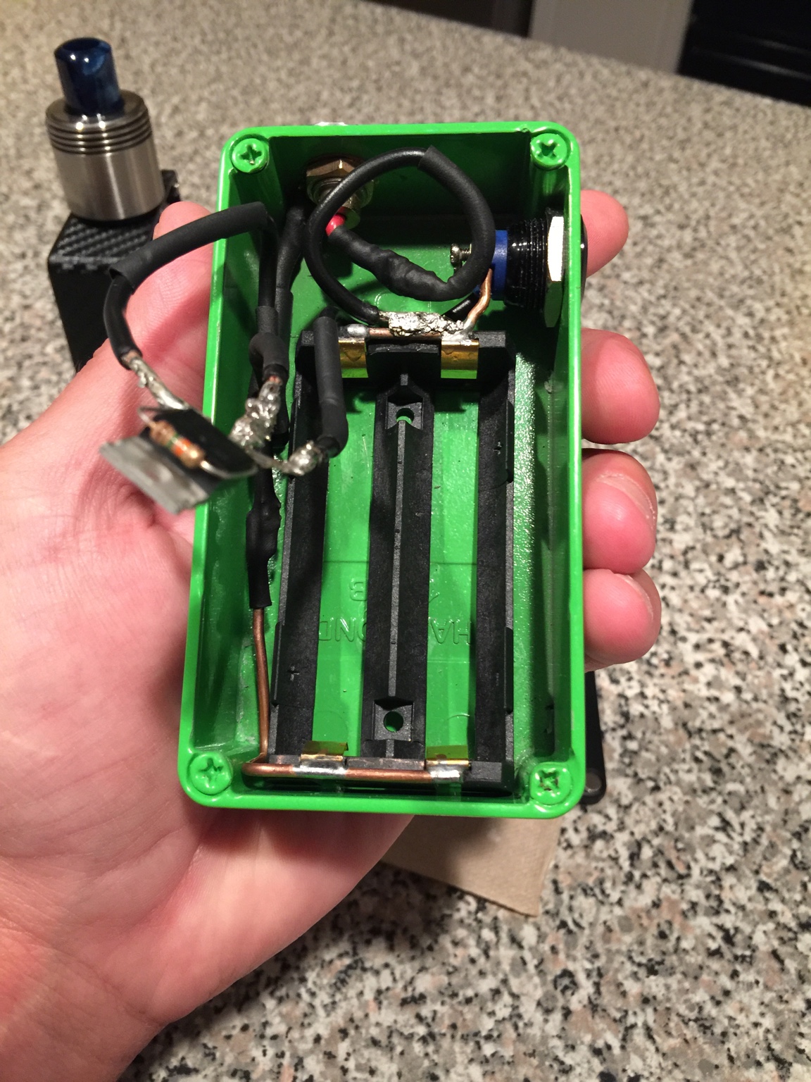
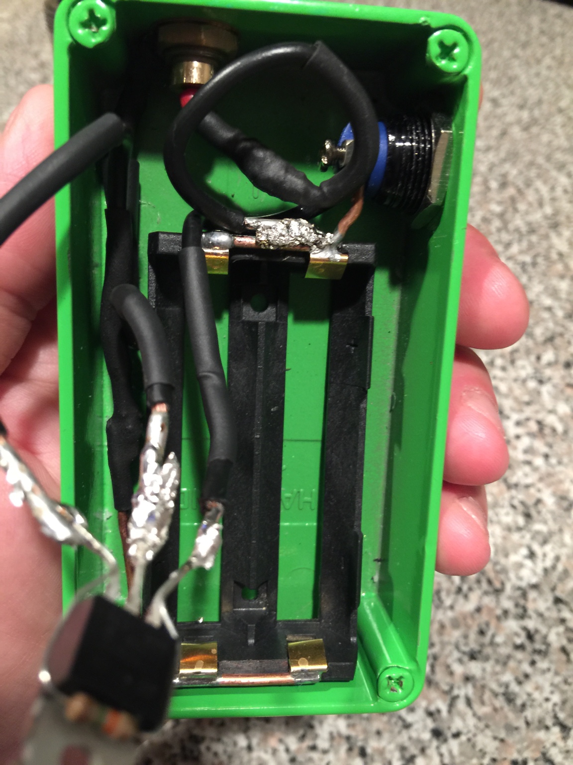
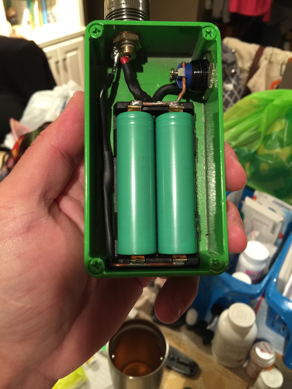
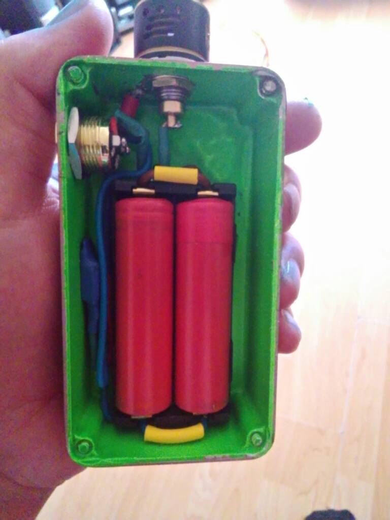
Hey guys! First 18650 dual parallel box mod build. I had 3 mosfets. I think I have burned up all three of them. I have been doing electrical work for about 15 years now so I know all about that. My box won't fire at all though. I think I have everything wired up correctly. All 14 gauge wire. Can anyone please help me. Do I just need to order more mosfets? Here's some pictures. Thanks in advance.
Sent from my iPhone using Tapatalk
There are schematics all over the Internet man Google is your friend..Can someone help me out with basic wiring of a mosfet for a box mod.
I am trying to use a mosfet in unregulated mode just to offset the AMP current form the button.
I am building a dual 18650 box mod, and would like to use the mosfet as most momentary switches are only rated to 3 AMPS
I've been all over Google and checked. I'm pretty sure I have I right. Just need to know I'm not going crazy. Lol
Sent from my iPhone using Tapatalk
Sent from my iPhone using Tapatalk
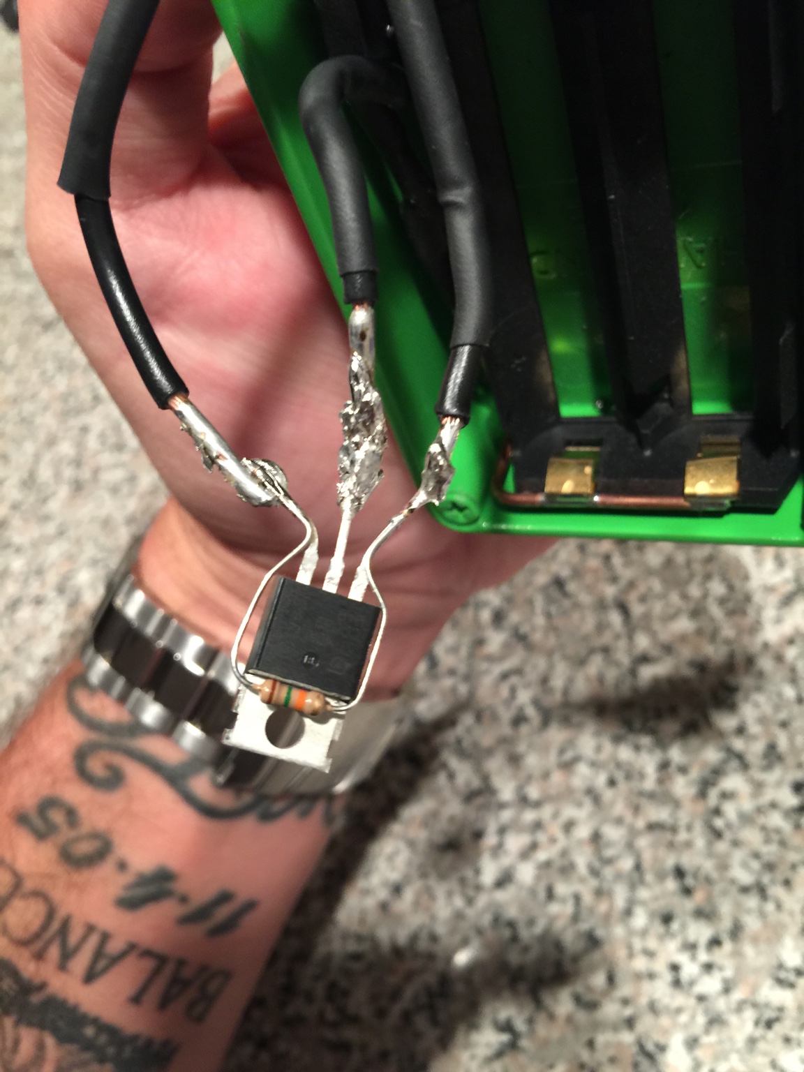
@Coletrain182 I have to be a dick here bro, those are by far the worst solder joints I ever saw. If this isn't a troll post I would have to honestly recommend giving up on box mod building man.
Lol thanks for the encouragement Wabah58! I'm just gonna start all over.
Sent from my iPhone using Tapatalk
Sent from my iPhone using Tapatalk
VapeTechnologies
VapeTechnologies LLC Advanced Custom Boxes
VU Donator
Member For 4 Years
Member For 3 Years
Member For 2 Years
Unlisted Vendor
Omg what did I just see... worthy of a screencap lol
You guys Crack me up")
You guys Crack me up
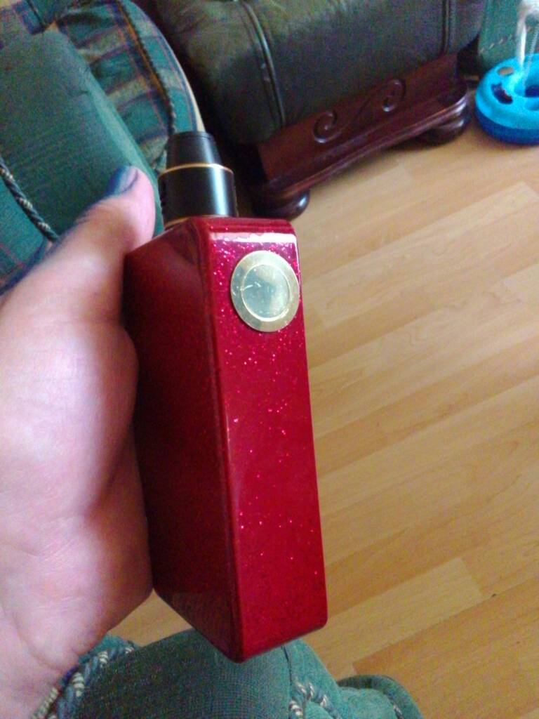
Damn was it that bad? Lol I got it working now. Just took the mosfet out and straight wired it. Works like a Charm now. .14 ohm build and chucks clouds for days.
Sent from my iPhone using Tapatalk
Sent from my iPhone using Tapatalk
Sent from my iPhone using Tapatalk
DIY FancyLights
Member For 4 Years
Bad solder jobs are enough to mess up a box mod, specially when working with parallel builds. The high currents involved greatly magnify the effects of the resistance in bad solder joints leading to weak pulls & even MOSFET overheating.
Also, uninsulated joints (like the ones in the first pictures) are very dangerous and could lead to shorts, unexpected firing, and battery overheating. There is a lot of power in those little batteries, think about safety first! It's not just about looks.
Also, uninsulated joints (like the ones in the first pictures) are very dangerous and could lead to shorts, unexpected firing, and battery overheating. There is a lot of power in those little batteries, think about safety first! It's not just about looks.
Thanks for the info. I appreciate it! I wasn't gonna leave those wire like that. I was gonna use some heat shrink just wanted everyone to see my awesome soldering job. Lol
Sent from my iPhone using Tapatalk
Sent from my iPhone using Tapatalk
wow great thread guys been reading the whole thing for like 3 days now its been like crack just learning and seeing everything everyone has come up with. I think I may try a pwm box for my first build. David do you sell that board and does it come populated
wow great thread guys been reading the whole thing for like 3 days now its been like crack just learning and seeing everything everyone has come up with. I think I may try a pwm box for my first build. David do you sell that board and does it come populated
PWM is just the best IMO, but might want to start with a basic parallel build first. Which ever way you decide to start, just take your time, since you read the whole thread you have a great start. GOOD LUCK! Post your build....
DIY FancyLights
Member For 4 Years
David will have to answer for himself about his PWM board.
I'm preparing to release kit for a 0.900"x0.392": board that has different characteristics from Davids board that can work with 2P/4P/2S/3S/4S and doesn't need any diodes on the pot like some of the 555 projects out there. More to follow once I get my bulk parts. I have the PCB's on hand and started testing last week, and have ordered bulk parts to help lower the cost for the kits.
I'm preparing to release kit for a 0.900"x0.392": board that has different characteristics from Davids board that can work with 2P/4P/2S/3S/4S and doesn't need any diodes on the pot like some of the 555 projects out there. More to follow once I get my bulk parts. I have the PCB's on hand and started testing last week, and have ordered bulk parts to help lower the cost for the kits.
DIY FancyLights
Member For 4 Years
Currently awaiting shipment confirmation on my bulk parts for the microPWM Kit. Keep in mind a magnifier, tweezers, fine tip soldering iron, and a steady hand will be needed to assemble the 6 SMD parts. Has space for some trimpots or easy wiring to an external pot, the fire switch must be off board. All holes for wires are along the edge of the board and can handle up to 22awg stranded or 20awg solid wire. Also has extra holes for additional connection to power/ground. The holes are also on a 0.1" grid so standard PCB headers can be soldered in (good for prototyping or people that want to be able to unplug their board).David will have to answer for himself about his PWM board.
I'm preparing to release kit for a 0.900"x0.392": board that has different characteristics from Davids board that can work with 2P/4P/2S/3S/4S and doesn't need any diodes on the pot like some of the 555 projects out there. More to follow once I get my bulk parts. I have the PCB's on hand and started testing last week, and have ordered bulk parts to help lower the cost for the kits.


 Y
Y
Only one battery shown in the sample usage, but can be 2P/3P/4P/2S/3S/4S, it can handle up to 18V and still works at 3.7V. One note, the pull down resistor on my microFET board does need to be change to 470K ohms. If using a TO-220 MOSFET, a 470K resistor is recommended instead of the 15K most unregulated mods use.
First draft of assembly instructions is at: www.diyfancylights.com/files/microPWM-5014-instructions.pdf, including the preliminary information on C1 & R1 frequency select (for people that don't like how it sounds, some PWM's whine, others buzz).
DIY FancyLights
Member For 4 Years
Sounds like some impressive wire, and not the type of thing that very many people could get their hands on. Having very flexible 14awg really helps for box mods as long as you also have good solder joints.
VapeTechnologies
VapeTechnologies LLC Advanced Custom Boxes
VU Donator
Member For 4 Years
Member For 3 Years
Member For 2 Years
Unlisted Vendor
Hey vapers and modders and aspiring assemblers, VapeTechnologies LLC here, checking in for another update
.jpg")
.jpg")
.jpg")
.jpg")
.jpg")
.jpg")
.jpg")
.jpg")
.jpg")
.jpg")
VapeTechnologies
VapeTechnologies LLC Advanced Custom Boxes
VU Donator
Member For 4 Years
Member For 3 Years
Member For 2 Years
Unlisted Vendor
I guess I have the time and patience to re-size a few more for the forum..
.jpg")
.jpg")
.jpg")
.jpg")
.jpg")
.jpg")
.jpg")
.jpg")
.jpg")
.jpg")
wow great thread guys been reading the whole thing for like 3 days now its been like crack just learning and seeing everything everyone has come up with. I think I may try a pwm box for my first build. David do you sell that board and does it come populated
If I have some boards available in the future I will let you know and yes it would be fully populated with all electrical components. The board with the screws and standoffs would have those included as well.
If you're too impatient too wait for me to get some boards assembled, I'd recommend Diy FancyLights mosfet board as well as his PWM board when available. Another source for some great boards would be ModPCB https://squareup.com/market/modpcb He usually offers more populated boards but is on vacation at the moment
DIY FancyLights
Member For 4 Years
For people that may be wondering about my timing on posting my PWM info, David and I have been sharing design ideas and feedback and David was privi to my preliminary information on this design and we have been influencing each others projects.
I just got in my bulk order of parts and I'm testing them, and will be opening up orders on my microPWM board on eBay soon. I'll give anyone here that contacts be directly discounts on the microFET boards or microPWM KITs.
I just got in my bulk order of parts and I'm testing them, and will be opening up orders on my microPWM board on eBay soon. I'll give anyone here that contacts be directly discounts on the microFET boards or microPWM KITs.
DIY FancyLights
Member For 4 Years
Other then I feel burnt out now and need to get my eBay listings for the microPWM up ... I'm officially moving my kit from the preorder to orderable now. For early adopters I'll continue to provide a range of 3 different C1 capacitors from 0.1uF to 0.47uF to help people choose the frequency (when combined with the pot value). Please note that Parallel batteries do work best at low frequencies (at low voltages the voltage booster driving the Gate needs more time to boost the voltage above the battery level).For people that may be wondering about my timing on posting my PWM info, David and I have been sharing design ideas and feedback and David was privi to my preliminary information on this design and we have been influencing each others projects.
I just got in my bulk order of parts and I'm testing them, and will be opening up orders on my microPWM board on eBay soon. I'll give anyone here that contacts be directly discounts on the microFET boards or microPWM KITs.
Please note ... anyone that is already a regular microFET buyer or buying 10 or more microFET's can ask for one microPWM KIT to play with for evaluation purposes
I'm also open to answering an questions people have ... but I probably should do that in a separate thread? Possibly under Regulated Mods since PWM is the most basic regulation? Sigh ... I suppose I'll have to post in Unlisted Vendor now as well my heads still spinning from all my testing!
At this point, you should just start a thread introducing this awesome new board you've created
I have a few of your microFETs. Installed one so far and it's such a huge help so I will get a PWM to try soon for sure!
Sent from my shoe phone using Tapa Toe Pro
I have a few of your microFETs. Installed one so far and it's such a huge help so I will get a PWM to try soon for sure!
Sent from my shoe phone using Tapa Toe Pro
DIY FancyLights
Member For 4 Years
Thanks ... since I'm newer to these forums advice is important ... but what I'll do is try to make it so other PWM stuff can be talked about as well since every design has it's good points and bad points.
But since it might end up being an Intro type thing in Newbie ... or go straight to Regulated?
... but what I'll do is try to make it so other PWM stuff can be talked about as well since every design has it's good points and bad points.But since it might end up being an Intro type thing in Newbie ... or go straight to Regulated?
How about a general thread like
"Talk about DIY PWM boards here"
Sent from my shoe phone using Tapa Toe Pro
"Talk about DIY PWM boards here"
Sent from my shoe phone using Tapa Toe Pro
Oh right, that has your name in it, we'll something like that....
Sent from my shoe phone using Tapa Toe Pro
Sent from my shoe phone using Tapa Toe Pro
DIY FancyLights
Member For 4 Years
Yea, I sort of got dragged into helping support vaping without trying because so many people were buy parts to use in their mods ... which led to the microFET and then the microPWM as well as expanding the product line. Some days I have too much practical experience with electronics (and computers) for my own goodOh right, that has your name in it, we'll something like that....
Sent from my shoe phone using Tapa Toe Pro
But, thats also why my projects are more modular in design, they aren't just for vaping, and will work where larger boards won't."The How-To & Why-To of PWM box mods" under this section? That will allow for a lot of useful input including links to various products as well as the pros & cons of PWM.
That sounds like a perfect title
VapeTechnologies
VapeTechnologies LLC Advanced Custom Boxes
VU Donator
Member For 4 Years
Member For 3 Years
Member For 2 Years
Unlisted Vendor
Got mine... so far I'm impressed, can't wait to see what these boards can deliver while taking up such little space. This is a MOSFET thread though, quite a historical one at best, so I'll post more over on @DIY FancyLights PWM thread. This thread is basically a timeline of modding advancements
.jpg")
.jpg")
.jpg")
Last edited:


VapeTechnologies
VapeTechnologies LLC Advanced Custom Boxes
VU Donator
Member For 4 Years
Member For 3 Years
Member For 2 Years
Unlisted Vendor
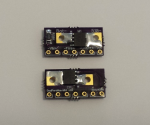
I mini dual parallel mosfet board I made
I was checking those out on OSHpark just the other day, David. Great job!
DIY FancyLights
Member For 4 Years
You can always write here about the microFET part One neat trick with that board is if you want parallel ... you stack two boards on top of each other (I recommend a slight gap) and just run the wires through both board ... and optionally remove one resistor.
One neat trick with that board is if you want parallel ... you stack two boards on top of each other (I recommend a slight gap) and just run the wires through both board ... and optionally remove one resistor.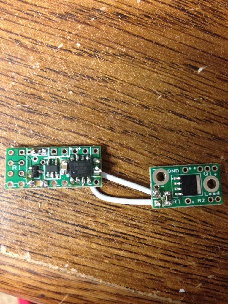
Do you have a picture or drawing of this board set up in series? I'm also confused about the center pin on the mosfet, do I cut it off? Just trying to figure out why my first attempt created a constant fire when I attached my atty. also due to the first board auto firing dose this mean all my pieces,(board,mosfet,switch,wires) are now bad and no good to reuse? I have no meter to check them.I have a new revision on these...much more simple setup
https://oshpark.com/shared_projects/qDRvdM0k
Unfortunately no...Do you have a picture or drawing of this board set up in series? I'm also confused about the center pin on the mosfet, do I cut it off? Just trying to figure out why my first attempt created a constant fire when I attached my atty. also due to the first board auto firing dose this mean all my pieces,(board,mosfet,switch,wires) are now bad and no good to reuse? I have no meter to check them.
Sent from my 9006W using Tapatalk
DIY FancyLights
Member For 4 Years
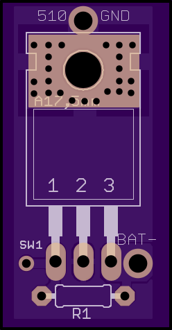
For that board, all three pins from the MOSFET go into the three holes directly below the MOSFET. A resistor (often 15K) goes into the two holes below that. If you forget the resistor, that can cause auto firing.
Thank You @DIY FancyLights for your response. The resistor was in place, so I'm not sure as if I've never had an issue from past custom boxes I've never used this board so I am looking for a drawing or schematic . My learning disability makes it hard to comprehend instructions, Any advice or drawings would be helpfullFor that board, all three pins from the MOSFET go into the three holes directly below the MOSFET. A resistor (often 15K) goes into the two holes below that. If you forget the resistor, that can cause auto firing.
Thought I'd have ago at making one few weeks ago turned out ok I think anyway.
 the wiring diagram I used.
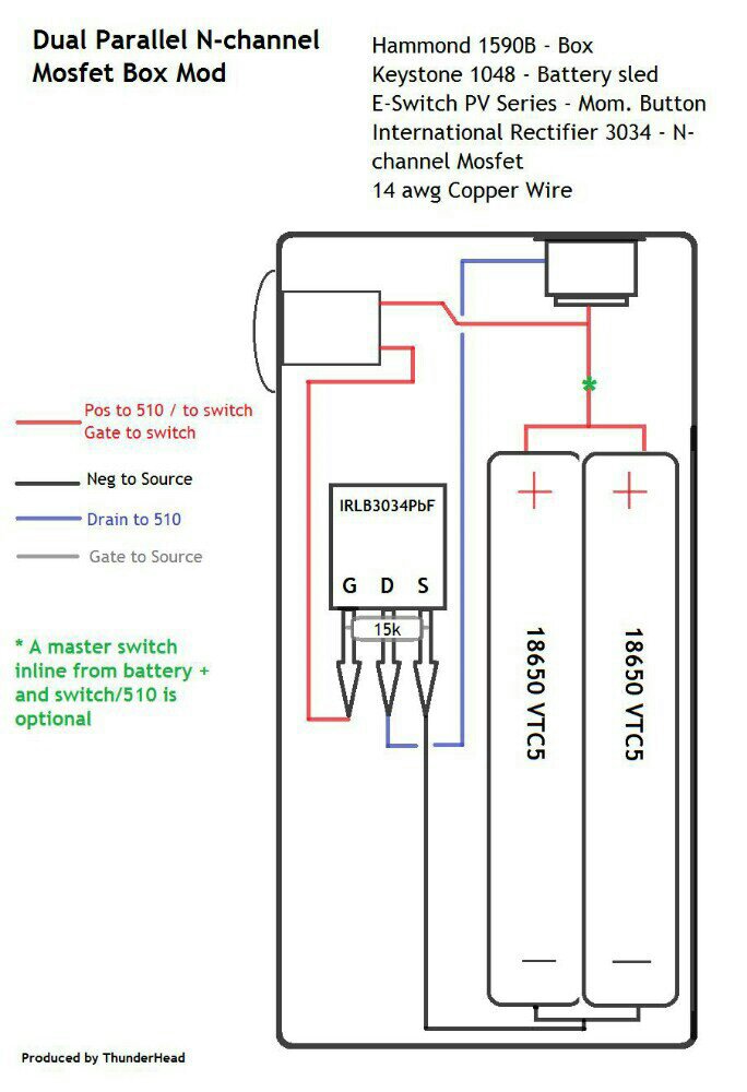
Sent from my P022 using Tapatalk
Sent from my P022 using Tapatalk
DIY FancyLights
Member For 4 Years
And the PCB that was being asked about is the same with one small exception, the wire in the middle (marked D) he needs to solder to the hole at the other end of the board near the tab. The G & S holes are the ones right near the their respective pins.
Not sur
And the PCB that was being asked about is the same with one small exception, the wire in the middle (marked D) he needs to solder to the hole at the other end of the board near the tab. The G & S holes are the ones right near the their respective pins.[/QUOTE
Not sure who your post was for, but if it was a response to me it has me confused a bit now, haha.
Not sure if your posting to me but now I am little lost on translationAnd the PCB that was being asked about is the same with one small exception, the wire in the middle (marked D) he needs to solder to the hole at the other end of the board near the tab. The G & S holes are the ones right near the their respective pins.