Become a Patron!

Basic MOSFET wiring

Resnik

Member For 4 Years
Member For 3 Years
Member For 2 Years
Member For 1 Year
Member For 5 Years
That's what I got last time. Got 10, and 10 3034 mosfets for like 23 bucks. But yeah they are only 12 cents each here. Only problem is they have at minimum 4.99 shipping. So a .12 cent part is going to cost over 5 bucks. Most places are going to be this way. Even eBay at the cheapest came in at like 3 bucks for 1 after shipping from some where in the US.

http://www.mouser.com/Search/Produc...irtualkey66200000virtualkey66-CMO1/21502JLFTR
 

Guest3123

Member For 4 Years
Member For 3 Years
Member For 2 Years
Member For 1 Year
Member For 5 Years
That's what I've been using. Cheap and simple with a rosin core.
http://www.mouser.com/Search/ProductDetail.aspx?R=4890-18Gvirtualkey59020000virtualkey590-4890-18G

PZQ4yBq.jpg

NsKfBVO.jpg

4KXuUmw.jpg


Figured out the issue with my mosfet. A stray wire was making contact from the negative side of the battery sled. Put a small piece of plastic under and now it fires perfect.
Looks like you really got it down pat. That's really reassuring, seeing that I'm really new to soldering & making my first box mod. If you could, can you point out to me what soldering iron your using for your builds? I watched some YouTube videos earlier, and what I learned or what I heard was anything from 25 Watt to 40 Watt soldering Iron. I have plenty of money, but The holiday season is right arround the corner, and I really don't want to spent that much like $129.99 for a soldering iron. I'll probably do a nicer box mod come January, but I really want to make a nice little box mod for the holiday season, so I can say I've accomplished something awesome this year.. Been wanting to do this for a few months now, just been a little nervious and didn't want to invest the money up until now. Now I think, as long as I can find a decent soldering iron that people are using, I'll go order everything and have a nice box mod done in no time flat.
 

Resnik

Member For 4 Years
Member For 3 Years
Member For 2 Years
Member For 1 Year
Member For 5 Years
lol not really. That was my first one and I messed it up by grounding it out and making it fire constantly lol. Then I realized what I had done. I am making more though, next is going to be a series mosfet box. Just waiting on the battery sleds to come in.

BUT I has this one and the LED lights help a lot. Also you want to grab a little thing called Helping hands. Really helps to have something to hold the parts your going to solder together.

Solder Iron:
http://www.mouser.com/ProductDetail/Weller/SP25NUS/?qs=sGAEpiMZZMtyU1cDF2RqUGInH7m/SpeN9ymPaQIH2F4=

Helping hands.
http://www.frys.com/product/5276537...cxL9lE-Fd__mMx6-1bVdlZik3Dim8z20IcxoCmLHw_wcB
 

Resnik

Member For 4 Years
Member For 3 Years
Member For 2 Years
Member For 1 Year
Member For 5 Years
I know I saw something like the helping hands at mouser, but not seeing it now. If you type in helping hands on ebay there are thousands and you can pick one up around 5 or 6 bucks with free shipping. That's the soldering iron I have, but mines 30 watts. Guess they changed it cause I can find that same one in 30 watts now.
 

Resnik

Member For 4 Years
Member For 3 Years
Member For 2 Years
Member For 1 Year
Member For 5 Years
I searched soldering irons on ebay and there was a set that came with solder, soldering iron, and helping hands for 14.99 with free shipping. For some reason it's not letting me link ebay stuff at all.
 

Guest3123

Member For 4 Years
Member For 3 Years
Member For 2 Years
Member For 1 Year
Member For 5 Years
I searched soldering irons on ebay and there was a set that came with solder, soldering iron, and helping hands for 14.99 with free shipping. For some reason it's not letting me link ebay stuff at all.
Awesome. Thank you.
 

Guest3123

Member For 4 Years
Member For 3 Years
Member For 2 Years
Member For 1 Year
Member For 5 Years
Yes, that image is correct for a basic wire up...you can use the metal tab on the top of the MOSFET as the drain, so the wire going to the 510 connector can come off the top

and Li Po batteries have VERY good high current C ratings

Awesome. Thank You.

As for the C Rating. It's absolutely ridiculous that these LiPo batteries can handle so much current. I've seen a battery I wanted to use for a very large box mod, that can handle like 500 amps or something like that. It had a C rating of like 90C, so with a 5,000mAh that's like 450 Amps. But that's just continuous. It's 180C 10 second burst, so like idk, 900 Amps. LOL !!

INSANE POWER ! Could easily vape at like 2kW.
 

TK Bisher

Member For 4 Years
Member For 3 Years
Member For 2 Years
Member For 1 Year
Member For 5 Years
That's what I've been using. Cheap and simple with a rosin core.
http://www.mouser.com/Search/ProductDetail.aspx?R=4890-18Gvirtualkey59020000virtualkey590-4890-18G

PZQ4yBq.jpg

NsKfBVO.jpg

4KXuUmw.jpg


Figured out the issue with my mosfet. A stray wire was making contact from the negative side of the battery sled. Put a small piece of plastic under and now it fires perfect.
I see on your battery that you have ground out spot. I had the same thing with my first mod, so I added a piece of ribbon to my sled to help pull them out evenly.
8b006c437cd073aebfe58e19314e11f8.jpg
 

Guest3123

Member For 4 Years
Member For 3 Years
Member For 2 Years
Member For 1 Year
Member For 5 Years
I see on your battery that you have ground out spot. I had the same thing with my first mod, so I added a piece of ribbon to my sled to help pull them out evenly.
8b006c437cd073aebfe58e19314e11f8.jpg


What's a ground out spot? Why is there a piece of tape or ribbon on the batteries? I don't understand.
 
lol not really. That was my first one and I messed it up by grounding it out and making it fire constantly lol. Then I realized what I had done. I am making more though, next is going to be a series mosfet box. Just waiting on the battery sleds to come in.

BUT I has this one and the LED lights help a lot. Also you want to grab a little thing called Helping hands. Really helps to have something to hold the parts your going to solder together.

Solder Iron:
http://www.mouser.com/ProductDetail/Weller/SP25NUS/?qs=sGAEpiMZZMtyU1cDF2RqUGInH7m/SpeN9ymPaQIH2F4=

Helping hands.
http://www.frys.com/product/5276537...cxL9lE-Fd__mMx6-1bVdlZik3Dim8z20IcxoCmLHw_wcB
Hey man so I'm new to all this too and I've read this whole damn thing lol I'm deff interested in how it all worked out with u and I'm also wondering if I'm supposed to wire the resister directly across the three prongs on the mosfet
 

Warhawk-AVG

Silver Contributor
Member For 5 Years
Yes, the prong on the left (pin 1) is the gate, the prong on the right (pin 3) is the source (aka battery negative), if you look at the above images, one half of the switch is tied to battery +, when you push that button, it creates the circuit, current then flows thru the resistor (but is heavily limited due to the 15k ohm resistance) to the gate ping and switch activating the MOSFET and allowing the high current path to drain (pin 2 or the metal tab) to be connected.
 

Guest3123

Member For 4 Years
Member For 3 Years
Member For 2 Years
Member For 1 Year
Member For 5 Years
Just a quick question. But with this N-Channel MOSFET (IRLB3034PbF), could I use a 7.4v Power supply to turn the MOSFET completely on?

The Specs are as follows. Data Sheet Here.

Vgs (th) : 1.0v - 2.5v
Vgs : ±20v (Does that mean give or take 20v ?)
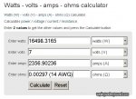
Rds ON : 1.4mOhm


It also talks more in dept about voltage, & it even talks about using up to 40v, so..

I could do this project... It's seems very doable. I studied a little bit today about MOSFETs, and supposidly the Vgs is like a electromechanical relay "COIL VOLTAGE". The coil voltage is the voltage required to power the coil to bring the switch to a close state. Activating the relays electromagnet, to close the switch. So that's what the Vgs is right? Do I follow the Vgs, or the Vgs (threshold) voltage?

I'm also looking at some of the other stuff on the data sheet, it's really fascinating what these MOSFETs can do.

ID @ TC = 25°C : Continuous Drain Current, VGS @ 10V (Silicon Limited) 343A

So they're using 10v at 25°C (77°F)..

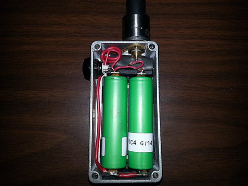
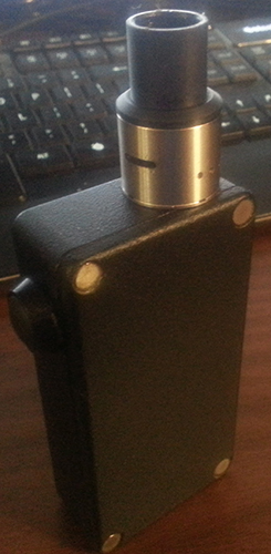
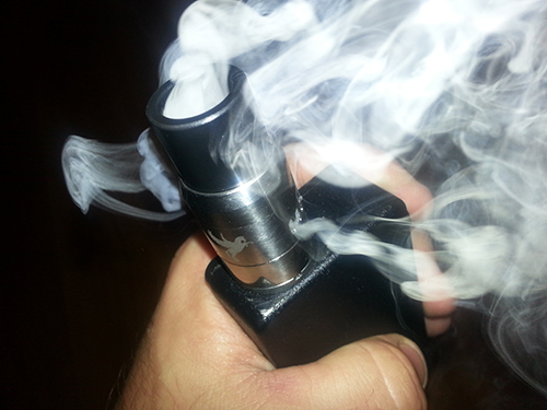
Anyways, I think it's ok to use 7.4v, but I just wanted to ask here, seeing that you guys have built Box Mods already, and I haven't. I'm still learning more & more about these MOSFETs, that's why I searched for some help.

I just need to know if 7.4v is ok to turn the MOSFET compleatly on. If you want to explain more about the datasheet specs, that would be really cool, and I'd really apreciate that. I'm actually going to search a little bit about reading a datasheet for MOSFETs on Google, and hopefully there's a video on YouTube too about it.

Ok, going back to studying now. Reading this. Here.
 

Resnik

Member For 4 Years
Member For 3 Years
Member For 2 Years
Member For 1 Year
Member For 5 Years
Hmms, I would say yeah I'll trade cause it's a match for what I spent just about for 1 mosfet and 1 resistor, but I live fairly far from you and with shipping you would be just about in the same boat. I don't know though it might be rather cheap. I'll have to check shipping to your area what not.
 

Wabah58

Silver Contributor
Member For 4 Years
Hmms, I would say yeah I'll trade cause it's a match for what I spent just about for 1 mosfet and 1 resistor, but I live fairly far from you and with shipping you would be just about in the same boat. I don't know though it might be rather cheap. I'll have to check shipping to your area what not.
Letter and a stamp.
 

Resnik

Member For 4 Years
Member For 3 Years
Member For 2 Years
Member For 1 Year
Member For 5 Years
lol yeah was reading on usps site. Not sure if it will be so simple. Lol I have a lot of experience in getting stuff shipped to me, but not much at all in sending stuff out. You would want it in a padded envelope right?
 

Resnik

Member For 4 Years
Member For 3 Years
Member For 2 Years
Member For 1 Year
Member For 5 Years
Seems like first class though does not go over 2.32 for small stuff like that.
 

Guest3123

Member For 4 Years
Member For 3 Years
Member For 2 Years
Member For 1 Year
Member For 5 Years
I love USPS. I have several Padded 9.5" x 12.5" Envolopes, small box, large boxes, and several stamps. I ordered like 15 padded envelopes (FREE), 15 Small Boxes, 10 Large Boxes..

For the Padded Flat Rate Priority (2-Day) Envolopes and small flat rate box it's like $5.30 if it's under 70 lbs. :)

10677078_10202657425905300_2118639137_o.jpg

10722893_10202636462701233_112009815_o.jpg

I love sending mail.. :)

I also have about 12 FOREVER (0.68c) Stamps too.

I think you can send the MOSFETs w/absolutely no problem with like 1 or 2 FOREVER stamps.

I think if it's under 1oz it's only like 0.69c. Just wrap them in a piece of ruled paper, and send em.

Easy as Pie.
 

Resnik

Member For 4 Years
Member For 3 Years
Member For 2 Years
Member For 1 Year
Member For 5 Years
Lol I just cut one of my padded envelopes that I got from something I bought online in half and taped them in there each in it's own bag. I'll just drop by the post office and see what's the cheapest way of sending it. Not sure if you can stamp a padded envelope.
 

Guest3123

Member For 4 Years
Member For 3 Years
Member For 2 Years
Member For 1 Year
Member For 5 Years
So I'm working on learning what AWG Wire I'll be using in my "FREEDOM HULK BOX MOD".

h12cblchrt-o_large.jpeg wiringdiagram.jpg

Turns out I'll probably be using 10 AWG (2.588mm | 0.1019"), If it's short, (0' - 2'), Looks like I can draw 140 Amps, but the other chart says 50-65 Amps. Which is fine..

IMG00000001 2014.10.21 09.32.00 PM.jpg

OR...

IMG00000001 2014.10.21 09.32.53 PM.jpg

Looks doable.
 

Resnik

Member For 4 Years
Member For 3 Years
Member For 2 Years
Member For 1 Year
Member For 5 Years
I use 10,12, and 14 gague wire on a daily basis In the electrical work I do. Your going to have a really tough time using 10 gague wire inside of a box mod. Hell even a hard time trying to solder it to the mosfet. Also there should not be more then 6 inches total wire length to any given point in the box and no more then a few second live time between puffs. I think you will be more then fine using 14 gague solid wire for this. Honestly ill never build a coil that hot. When you make coils that low your getting your more burning your juice and turning it into a gas rather then a vapor. Thats not to healthy. But each to their own. Just my 2 cents. Also its not recommended to go much under .5 ohms on a mosfet. Then as well if you build a series box mod @ 8.4v a .5 ohm build would be super hot and would be better to stay at .8 or above.
 

Guest3123

Member For 4 Years
Member For 3 Years
Member For 2 Years
Member For 1 Year
Member For 5 Years
I use 10,12, and 14 gague wire on a daily basis In the electrical work I do. Your going to have a really tough time using 10 gague wire inside of a box mod. Hell even a hard time trying to solder it to the mosfet. Also there should not be more then 6 inches total wire length to any given point in the box and no more then a few second live time between puffs. I think you will be more then fine using 14 gague solid wire for this. Honestly ill never build a coil that hot. When you make coils that low your getting your more burning your juice and turning it into a gas rather then a vapor. Thats not to healthy. But each to their own. Just my 2 cents. Also its not recommended to go much under .5 ohms on a mosfet. Then as well if you build a series box mod @ 8.4v a .5 ohm build would be super hot and would be better to stay at .8 or above.

Okay. Then I'll just use 14 AWG. I don't think I'll be using less than 3 - 4" of wire, per connection.
 

Guest3123

Member For 4 Years
Member For 3 Years
Member For 2 Years
Member For 1 Year
Member For 5 Years
Okay. Then I'll just use 14 AWG. I don't think I'll be using more than 3 - 4" of wire, per soldered connection.

Is there a way to calculate the amount of current that can flow threw per Inch (L) of wire? I found some charts, it says that 10 Guage will only carry 30 Amps of current, but that's rated for 1000 FT.

I wanted to know how much current a given diameter of wire (AWG) can handle, without it heating up, or causing the insulation on the solid copper wire to melt.
 
Last edited:

Resnik

Member For 4 Years
Member For 3 Years
Member For 2 Years
Member For 1 Year
Member For 5 Years
Hell I use that 18 and other then the atomizer getting hot the box wires still feel cold on a .4 ohm build.
 

Resnik

Member For 4 Years
Member For 3 Years
Member For 2 Years
Member For 1 Year
Member For 5 Years
30 amps on 10 gague is a NEC national rating. Basically that is like a guaranteed amperage it can handle. Kinda like 1000 pound rated rope is gaurantied @ 1000 pounds but is tested and can handle 5000 pounds.

I like the ease of 18 but the higher rating of 14 so my next one will be 16 right in the middle.
 

Resnik

Member For 4 Years
Member For 3 Years
Member For 2 Years
Member For 1 Year
Member For 5 Years
14 would burn at that current. It might be able to handle for a second but would soon heat up and break. Thats a really messed up calculation there. The thing is with both dc and ac its the amps that hurt you. You can run huge amounts of volts through small wires as long as the amps are low. As soon as you start putting a load on it, it starts to build up heat and that copper starts to break down when it hits it melting point.
 

Warhawk-AVG

Silver Contributor
Member For 5 Years
Truthfully, your wires are what 2-3" at most? You could probably get away with 18-22ga wire w/ the runs being that short

One of my other hobbies is ULTRA high power flashlights (think over 100K lux [measurement of light]...using the AOD510 and cree XM-L emitters (multiple emitter builds [most one guy pushed on a single emitter was 7.5A]) we have currents of upwards of 20A on some builds

The Amps thru the wire is what cause it to heat up...not the voltage
 

Guest3123

Member For 4 Years
Member For 3 Years
Member For 2 Years
Member For 1 Year
Member For 5 Years
...
 
Last edited:

Guest3123

Member For 4 Years
Member For 3 Years
Member For 2 Years
Member For 1 Year
Member For 5 Years
...
 
Last edited:

Guest3123

Member For 4 Years
Member For 3 Years
Member For 2 Years
Member For 1 Year
Member For 5 Years
The nichrome wire heated up more because of the high resistance compared to the copper wire resistance

To figure out how hot it will get based upon resistance per foot x current...well...TONS of math on that

http://hyperphysics.phy-astr.gsu.edu/hbase/electric/restmp.html
Yep! TONS of Math is EXACTLY Right. WOW, Holy Crap !

I studied ("Current Carrying Capacity" for like 2+ hours, and WOW.

I'll test out the wires are various current ratings (5Amps to IDK 50+ Amps) and see if the wires heat up. The math required I've discovered involves PREECE Equations and etc.

Probably test my circuit designs on a solderless breadboard first.

I'll just use 14 or 16 AWG Wire. :)
 
Last edited:

Resnik

Member For 4 Years
Member For 3 Years
Member For 2 Years
Member For 1 Year
Member For 5 Years
Bread boards generally only go 20 gauge and higher. I know mine would have issues with 16 and 18. I think you would be fine with 18 in all honesty. I know I run .2 parallel 24 gauge and .4, 8 wrap 24 gauge and never have had an issue. Never even got pee pee warm.

@ Wabah58 >.> Sent the package by the way.
 

Wabah58

Silver Contributor
Member For 4 Years
Bread boards generally only go 20 gauge and higher. I know mine would have issues with 16 and 18. I think you would be fine with 18 in all honesty. I know I run .2 parallel 24 gauge and .4, 8 wrap 24 gauge and never have had an issue. Never even got pee pee warm.

@ Wabah58 >.> Sent the package by the way.
Cool thanks so much, sent yours today too.
 

Resnik

Member For 4 Years
Member For 3 Years
Member For 2 Years
Member For 1 Year
Member For 5 Years
Welcome. Hope it woks out for you.
 

Guest3123

Member For 4 Years
Member For 3 Years
Member For 2 Years
Member For 1 Year
Member For 5 Years
Bread boards generally only go 20 gauge and higher. I know mine would have issues with 16 and 18. I think you would be fine with 18 in all honesty. I know I run .2 parallel 24 gauge and .4, 8 wrap 24 gauge and never have had an issue. Never even got pee pee warm.

@ Wabah58 >.> Sent the package by the way.

Awesome, thanks for the experienced advice & help.
 
I made a Vaping Underground MOSFET box mod board, if interested, preliminary design...I might end up having to make another via hole for another wire, otherwise you will have to make a "Y" + battery cable...

2 layer board of 0.62x1.19 inches (16x30mm). $3.70 for three.

Top:
i.png


Bottom:
i.png


Any of the TO220 style N-Type MOSFETS, and any 1/4 watt resistor, cut the center leg, it's ground...that huge ground plane is now ground, solder any momentary switch on SW1 and SW2, solder the BAT+ to the center pin on the 510 connector, solder GND to the 510 outer housing....fire that puppy up :)

Here are some VERY good TO220 style MOSFETS
I just ordered a batch of these...so SW1 is positive so I can wire up the LED in my angel eye switch right? No need for a resistor between the switch and the board?
 

Resnik

Member For 4 Years
Member For 3 Years
Member For 2 Years
Member For 1 Year
Member For 5 Years
I see on your battery that you have ground out spot. I had the same thing with my first mod, so I added a piece of ribbon to my sled to help pull them out evenly.
8b006c437cd073aebfe58e19314e11f8.jpg
Yeah those batteries have been through hell lol. The snags in the heat shrink was from things other then the contacts in the box lol. Kinda rough on my vape gear. Sorry I missed you posting on this and just now saw it. The ribbon is a good idea though and I'll be adding that to my box. I did however fix the problem with those connection tabs. There are two bends in the metal one at the top where the contact turns down and then a second one where it turns back into the contact. That second one is supposed to keep it from catching on battery sleeves, but does not work well. I took it and bent it further in and now it does not catch. This problem happens on just about all the battery sleds I've seen. 1048 keystones and other brands.
 

Wabah58

Silver Contributor
Member For 4 Years
I almost got a Darkhorse to modify for a bottom feed squonk box. I saw some people having success modifying them for bottom feeders. But im really happy with the Big Dripper so squonk box is out. LOL.

Nice vape chuckin there. :eek:
 

Resnik

Member For 4 Years
Member For 3 Years
Member For 2 Years
Member For 1 Year
Member For 5 Years
I've got a big dripper too. Like the flavor I can get off of it and it blows nice clouds. Even when built with a hot coil the BD remains a really cool vape. It stays on my "out to work" vape machine.
 

Resnik

Member For 4 Years
Member For 3 Years
Member For 2 Years
Member For 1 Year
Member For 5 Years
Looking good. How are you liking the series power?
 

WescottsVape

Member For 4 Years
Member For 3 Years
Member For 2 Years
Member For 1 Year
Member For 5 Years
Hey everybody, Ive been doing a lot of research about putting together my first box mod and am now just waiting on the parts. I'm gunna be running dual 18650's in parallel with a mosfet to save my switch. But now I have a wiring question... I want to use solid 16 gauge copper wire, but I don't want to solder a lead from the switch directly to the lead going from the pos of the batteries to the 510. Could I run the wire from the switch through the pos connection o the battery sled and then route it up to the 510 adapter?
 

VU Sponsors

Top