Become a Patron!

Help building an unregulated 18650 in series mod (8.4 volts)

d00hickey

Member For 4 Years
Member For 3 Years
Member For 2 Years
Member For 1 Year
Member For 5 Years
I was originally planning to build a regulated mod but decided I would rather build an unregulated 18650 in series box mod. I want to keep it as simple as possible, I want to be able to draw 30 amps at 8.4 volts at the most with it. Does anyone know where I can find some basic plans/parts list for these? I imagine a 30 amp switch will be hard to find but I see these types of mods for sale often. I'm open to using a wood box, or a Hammond style (a cooper box would be sweet if I could figure out how to use the box itself as part of the circuit).

Any hoo, info would be appreciated. Just as a note i have experience with parallel/stacked mods and I know the limitations of such systems. I do not however know the limitations of some of the components, like the switch, for the type of project I want to do.

I quite like the look and simplicity of this mod I found on Ebay but I worry that switch, 510, and wires may not hold up to up to 30 amps. Maybe I'm wrong.
 

d00hickey

Member For 4 Years
Member For 3 Years
Member For 2 Years
Member For 1 Year
Member For 5 Years
So far my parts list is for my dual 18650, unregulated, 8.4 volt cloud monster:

My hamond box- My Batt Sled- And the wire I plane to use-
I need to still pick a 510 and a switch, I'm having a hard time finding a switch because I'm confused about whether or not I need the switch to handle the up to 30 amps, or if it's less important due to the fact it's making contact on the negative line of the mods circuit. Any help would be greatly appreciated.

For the 510, I'm debating getting the floating/spring 510 from Fat Daddy but a mechanically adjustable 510 would be great. any help would be greatly appreciated.
 

Wabah58

Silver Contributor
Member For 4 Years
If your doing a build with a Mosfet (Which I recommend) you can get a very small switch to free up room. I like the mini tactile switch like the Cana mods. Can't go wrong with the Fatdaddy 510. If you want a little lower profile good 510 the Varitube is very nice too. 14 ga solid is awesome for these builds, but if you have a B box there is loads of room in there.

http://www.varitube.com/510-Connector--Self-adjusting-Center-Pin--14mm-22mm-285mm_p_141.html
 
Last edited:

Wabah58

Silver Contributor
Member For 4 Years
Here is a box I just finished. It's a Hammong G box, smaller than the B.
Keystone 1048 Dual battery sled
Fat Daddy Vapes 510 Connector with extension ring
Evolv USB charging board
International Rectifier IRLB3034 Mosfet
15K Ohm resistor 1/2 watt (Only need 1/4 watt little smaller too)
Domed Tactile Switch
Door and box magnets.
Mine is a parallel build though, not series.

Box3.jpg Box4.jpg charging.jpg sled3.jpg
 
Last edited:

OB61887

Am I saying meow?
Silver Contributor
Member For 4 Years
Member For 3 Years
Very nice. I want to make a box mod, but I want to make one with magnets instead of screws. You know of any project boxs that don't have screws? I know I can fill the holes and just attach magnets, but I would like to not have the screw posts on the inside if possible.
 

OB61887

Am I saying meow?
Silver Contributor
Member For 4 Years
Member For 3 Years
I was hoping to do something similar to Seigil 100W where there are magnets on moth sides.
 

d00hickey

Member For 4 Years
Member For 3 Years
Member For 2 Years
Member For 1 Year
Member For 5 Years
I like that and I'll probably get the smaller box but I want it to be as simple as possible (I just love simplicity). Definitely series to double the voltage. My question is how many amps would the switch need to be rated for for me to do builds for up to 30 amps? I will be using it occasionally for big clouds only with something like my Dodge, or Dark Horse with builds as low as .3 (8.2 volts). I read somewhere that since the switch will be on the negative line in the circuit it doesn't need to be rated for 30 amps, I just want some second opinions on that.
 

Wabah58

Silver Contributor
Member For 4 Years
I like that and I'll probably get the smaller box but I want it to be as simple as possible (I just love simplicity). Definitely series to double the voltage. My question is how many amps would the switch need to be rated for for me to do builds for up to 30 amps? I will be using it occasionally for big clouds only with something like my Dodge, or Dark Horse with builds as low as .3 (8.2 volts). I read somewhere that since the switch will be on the negative line in the circuit it doesn't need to be rated for 30 amps, I just want some second opinions on that.
Are you gonna use a mosfet? If yes, you can use a under rated very small switch since the mosfet takes the heavy amps off the switch.

If you are NOT going to use a mosfet, a 30 amp switch is going to be huge, you will have to do some work shaving down the battery sled and box if going in a G box.
 

d00hickey

Member For 4 Years
Member For 3 Years
Member For 2 Years
Member For 1 Year
Member For 5 Years
I'll look into the Mosfet. Wabah58, do you know of a simple schematic or a part list that shows me how to put one together. I've built a few DNA boxes so I know my way around pretty good but I want to make sure I know my stuff when I'm dealing with this much power.

This might be a stupid question but, if I built my box basically the same as yours but in series, and without the evolve USB board would it work without problems. I quite like the look of yours and it's basically exactly what I'm looking for.
 
Last edited:

Wabah58

Silver Contributor
Member For 4 Years
You should be fine, I only recommend building with a mosfet though. Doing a series build in a G box also a little easier to route wires and look good.

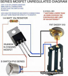
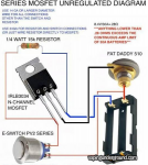
The Vapingunderground covered up the bottom wires :(
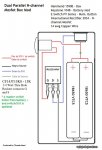
But the 2 bottom leads on the battery sled just connect together with 1 wire.

Series.PNG

Series.PNG
 

d00hickey

Member For 4 Years
Member For 3 Years
Member For 2 Years
Member For 1 Year
Member For 5 Years
That looks brilliant. So I should use 14g cooper wire to bridge the positive and negative at the base of the sled, and 24g cooper to connect the button leads to the resistor, negative and positive lines?

I plan to place the order today or tomorrow.

3 more questions: Is the resistor required for operation or could it be bypassed for simplicity? if yes what does the resistor do?
2nd question, anyone know of a carbon fiber box similar in size to the Hammond G or B?
3 question: can I use any 2 amp switch, similar to the dome switch you have on your mod?
 
Last edited:

Wabah58

Silver Contributor
Member For 4 Years
That looks brilliant. So I should use 14g cooper wire to bridge the positive and negative at the base of the sled, and 24g cooper to connect the button leads to the resistor, negative and positive lines?

I plan to place the order today or tomorrow.

3 more questions: Is the resistor required for operation or could it be bypassed for simplicity? if yes what does the resistor do?
2nd question, anyone know of a carbon fiber box similar in size to the Hammond G or B?
3 question: can I use any 2 amp switch, similar to the dome switch you have on your mod?

Yes on 14 ga wire to bridge the neg and positive on bottom of sled. I use 14 ga solid for everything all connections, but technically you can use the lower ga wire off the fet, to switch. Now I recommend just using 14 ga solid for EVERYTHING, keeps your shopping list a bit more easy, and bigger is better on wire, yet still looking and performing excellent. Up to you though.

You WANT that resistor. That helps with shutting off the gating of the fet. Think of it like this. When you let go of the fire button you want the power is stop immediately, not 5 seconds after. That resistor will aid in stopping the gating action of that fet.

If you use a fet YES you can use any switch you want. The smaller the switch will make it much easier for you when it comes to tucking your wires into a nice looking tidy fit. Huge button you will have some extra work to do and makes it a pain in the ass to route your wires past. I love the mini tactile switches man they tiny. For me the last 2 solder connections I do on by build is the switch.

NOTES: Im no pro, and I dont sell for money, I just made a few boxes for a couple friends and me. I have access to top rate soldering equipment, and have soldered hundreds of control boards at work, and have a electrical engineer at work to bounce ideas off of when I needed it. That being said I have learned a couple things along the way that I will gladly share with you. First couple boxes I did I used 14 ga stranded wire, I switched to solid because the solid holds sharp bends very good and tight, and I like my wires and bends to look tidy and tight. The stranded wire when you bend it real sharp, it tends to look rounded and doesnt hold it's shape sometimes. (Just personal preference)

Mosfets are cheap but there are MANY people that burn them up before even geting them in their box. The most tricky thing in building a box mod is doing the fet and resistor without burning it up soldering. Make sure you have your soldering skills at peak when you go to solder the fet/resistor/wire. I will attach a picture at the end of this post, how I wire mine. I solder the resistor and wire to fet in 1 shot. I have the fet holding with a pair of aligator clips acting as a heat sink, so I dont burn my fet during soldering. I recommend getting a few mosfets if you think your soldering skills might not be up to par. They are very cheap, incase you get it to hot and burn it up on first solder try. Using a helping hands holder with the aligator clips for that fet during soldering is recommended for taking the heat off that fet body during soldering.

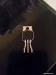
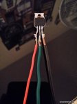
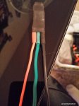
The first 2 fet pictures below are the way to run your leads best for a series build. The last picture of the heat shrinked fet is how I do mine for a parallel build.After each lead is properly heat shrinked individually, I use 1 big piece of heat shrink to do the whole fet and resistor.
People are hoarding all the fets building these boxes, causing massive shortages. You might be forced to use ebay to get them. I had to get my last 2 off ebay.
This is the one you have to get
http://my.mouser.com/ProductDetail/International-Rectifier/IRLB3034PBF/?qs=sGAEpiMZZMshyDBzk1/Wi5%2bqVgN3%2bWS8iNZUeqPPDAc=


Do not get the cheap ones from china vendors!!!

1010372_1498556650407037_1584802459776683735_n.jpg 10409153_1498556670407035_5993763305552104853_n.jpg99.jpg10698620_1498556697073699_2880007743870621102_n.jpg
 
Last edited:

Warhawk-AVG

Silver Contributor
Member For 5 Years
Yes on 14 ga wire to bridge the neg and positive on bottom of sled. I use 14 ga solid for everything all connections, but technically you can use the lower ga wire off the fet, to switch. Now I recommend just using 14 ga solid for EVERYTHING, keeps your shopping list a bit more easy, and bigger is better on wire, yet still looking and performing excellent. Up to you though.

You WANT that resistor. That helps with shutting off the gating of the fet. Think of it like this. When you let go of the fire button you want the power is stop immediately, not 5 seconds after. That resistor will aid in stopping the gating action of that fet.

If you use a fet YES you can use any switch you want. The smaller the switch will make it much easier for you when it comes to tucking your wires into a nice looking tidy fit. Huge button you will have some extra work to do and makes it a pain in the ass to route your wires past. I love the mini tactile switches man they tiny. For me the last 2 solder connections I do on by build is the switch.

NOTES: Im no pro, and I dont sell for money, I just made a few boxes for a couple friends and me. I have access to top rate soldering equipment, and have soldered hundreds of control boards at work, and have a electrical engineer at work to bounce ideas off of when I needed it. That being said I have learned a couple things along the way that I will gladly share with you. First couple boxes I did I used 14 ga stranded wire, I switched to solid because the solid holds sharp bends very good and tight, and I like my wires and bends to look tidy and tight. The stranded wire when you bend it real sharp, it tends to look rounded and doesnt hold it's shape sometimes. (Just personal preference)

Mosfets are cheap but there are MANY people that burn them up before even geting them in their box. The most tricky thing in building a box mod is doing the fet and resistor without burning it up soldering. Make sure you have your soldering skills at peak when you go to solder the fet/resistor/wire. I will attach a picture at the end of this post, how I wire mine. I solder the resistor and wire to fet in 1 shot. I have the fet holding with a pair of aligator clips acting as a heat sink, so I dont burn my fet during soldering. I recommend getting a few mosfets if you think your soldering skills might not be up to par. They are very cheap, incase you get it to hot and burn it up on first solder try. Using a helping hands holder with the aligator clips for that fet during soldering is recommended for taking the heat off that fet body during soldering.

The first 2 fet pictures below are the way to run your leads best for a series build. The last picture of the heat shrinked fet is how I do mine for a parallel build.After each lead is properly heat shrinked individually, I use 1 big piece of heat shrink to do the whole fet and resistor.
People are hoarding all the fets building these boxes, causing massive shortages. You might be forced to use ebay to get them. I had to get my last 2 off ebay.
This is the one you have to get
http://my.mouser.com/ProductDetail/International-Rectifier/IRLB3034PBF/?qs=sGAEpiMZZMshyDBzk1/Wi5%2bqVgN3%2bWS8iNZUeqPPDAc=


Do not get the cheap ones from china vendors!!!

View attachment 7434 View attachment 7436View attachment 7437View attachment 7438

Awesome!

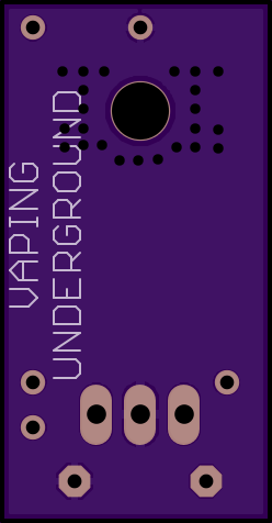
Would a small PCB where you could solder all that to, then with a single piece of 18650 wrap help?

i.png
i.png


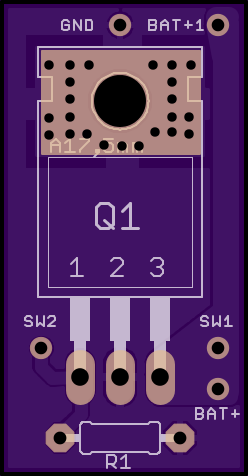
It's a small PCB that everything solders to, I might need to open up the VIA's (solder holes in board) a bit to allow for larger wires
0.62x1.19 inches (15.77x30.28 mm)

Just an experiment to see if I could make a manufactured board in lieu of the awesome DIY stuff (I also may need to double check the board layout and stuff [the above diagram is much simpler than my design])...that walkthru of images above is AWESOME...pure brilliance! (I even think I can make is smaller using SMD components (D-Pak) rather than the large TO220 package MOSFET
 
Last edited:

Warhawk-AVG

Silver Contributor
Member For 5 Years
I am going to modify it

coincidentally, the center pin on the TO220 IC, you can solder the top ground wire (that goes to the 550 to the metal tab instead of the center pin, this give only 2 wires on bottom and one on top

series-png.7426
 

Warhawk-AVG

Silver Contributor
Member For 5 Years
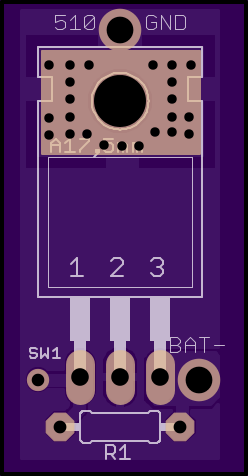
ok...modified the board

i.png
i.png


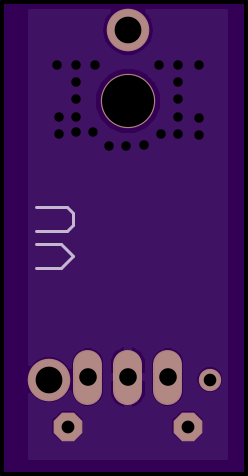
OK...it is pretty much the exact same setup as above, only 3 wires need to be soldered, the battery - and Switch wire on bottom, the 510 ground wire on top.

The VIA's have been enlarged to 1.7mm to be able to fit 14ga wire in them, the SW1 VIA is 24ga...the board is just slightly larger than the width of the TO220 chip and just a tiny bit longer, but now with a single piece of 18650 wrapping shrinkwrap you can cover the entire setup (not multiple strips of heatshrink tubing)

2 layer board of 0.62x1.19 inches (16x30mm). $3.70 for three.
 

d00hickey

Member For 4 Years
Member For 3 Years
Member For 2 Years
Member For 1 Year
Member For 5 Years
Thanks again guys, this advice has been super helpful. My only problem is I keep changing my mind about stuff I want to do. Now I'm thinking I want to buy or build a wood box instead of the Hammond. Has anyone here ever seen a nice wood (ceder, maple, etc) that has the same dimensions as the Hammond G box? I wouldn't mind trying to build one but I have this fear I'm going to mess up and/or hate the device to put so much work into it.

I have the sled, a super nice button, mosfets (4 in case I destroy one or two), a ton of 1/4W 15k Ohm resistors and all the wires.
I still need to get a 510 and the box.

An adjustable or floating 510 is required because gaps erk the hell out of me, I'm leaning toward the one Wahbah58 recommended .
 

Wabah58

Silver Contributor
Member For 4 Years
A wood box usually needs a longer 510, which Fatdaddy makes one with a longer shank just for woodies.

At some point you have to say "FUCK IT, IT WILL EITHER WORK OR IT WONT"

LOL!
 

Wabah58

Silver Contributor
Member For 4 Years
Awesome!

Would a small PCB where you could solder all that to, then with a single piece of 18650 wrap help?

i.png
i.png


It's a small PCB that everything solders to, I might need to open up the VIA's (solder holes in board) a bit to allow for larger wires
0.62x1.19 inches (15.77x30.28 mm)

Just an experiment to see if I could make a manufactured board in lieu of the awesome DIY stuff (I also may need to double check the board layout and stuff [the above diagram is much simpler than my design])...that walkthru of images above is AWESOME...pure brilliance! (I even think I can make is smaller using SMD components (D-Pak) rather than the large TO220 package MOSFET

I want to start out by stating again: Im no pro, nor do I sell boxes for money, but I know my way around tight fitting boxes, safety, and making something Nice. With all that being said I have some input.

If you could get that fet board down to just barley wider than the fet itself. I would test it using 1 G box making sure it would tuck in the side with all the wires in place and shrink wrapped. Second test would be in a B box with dual 26650, where there is only room above the batteries to carry the fets.
In both cases i would do a 10 minute continuous. low ohm coil burn for torture test.

Im sure you have tested them in dual 18650 B boxes where there is tons of room for anything?

I would maybe consider mounting one on bottom like I did on the USB charging board of my last box, in a G. On that I had the room, I soldered my wires on board, then sanded the solder connenction almost flat with the board. I cut a very thin piece of clear rigid plastic the exact size of the board. Very thin coat of epoxy under board on to plastic. Then thin coat of epoxy under plastic to box. It's very stable, cause I've pluged my usb cable in there probably 100 times so far. My batteries have never came out of my last box, after I tested them on my meter for even charging and consumption.

I did watch the progression of PCB boards development of their mechanical board box all in one. I don'treally get the market for that but can possibly see a market for your fet board, but im sure you know, it has to be micro small, and no wider that the fet itself if at all possible.

I have never fried a fet, but a lot of people do, so could be some interest in your product, Im sure there will be traces on the back of the board, for the fet to resistor?? The hard bend from solid 14 ga solid off of that board will be a factor too.
 
Last edited:

Wabah58

Silver Contributor
Member For 4 Years
Im thinking about doing 1 more box. Hammond B box (Orange), dual 26650. Only room will be above the batteries, to fit fet and usb charging. Will use the new Vape3d battery sled, usb charge board from evolv. Going to get the Varitube 510, this time. 2 26650's in a B there is no room at all on the sides for anything.
 
Last edited:

d00hickey

Member For 4 Years
Member For 3 Years
Member For 2 Years
Member For 1 Year
Member For 5 Years
All the goodies are finally in the mail from various vendors, it wasn't easy because I guess the demand for this stuff is absurd, I saw people selling the 1590G and battery sleds for over $30. I ended up getting everything I wanted for under $30 though, it just took some shopping around.

This probably won't be my last stupid question but; does the resistor need to be placed in a specific orientation to the gate and the source of the mosfet? or does it work either way?
 

Wabah58

Silver Contributor
Member For 4 Years
All the goodies are finally in the mail from various vendors, it wasn't easy because I guess the demand for this stuff is absurd, I saw people selling the 1590G and battery sleds for over $30. I ended up getting everything I wanted for under $30 though, it just took some shopping around.

This probably won't be my last stupid question but; does the resistor need to be placed in a specific orientation to the gate and the source of the mosfet? or does it work either way?
Will work either way.
 

MrFixIt

Member For 4 Years
I am looking for a wiring diagram that shows the best way to wire a lighted switch like the ones from adafruit. Found some posts but they are not good examples. Any suggestions?
 

d00hickey

Member For 4 Years
Member For 3 Years
Member For 2 Years
Member For 1 Year
Member For 5 Years
I received most of the parts for my box build, except the Fat Daddy 510. The button I received came with a small o ring and I can't figure out where it goes.
 

MrScaryZ

VU Donator
Platinum Contributor
Member For 5 Years
I was originally planning to build a regulated mod but decided I would rather build an unregulated 18650 in series box mod. I want to keep it as simple as possible, I want to be able to draw 30 amps at 8.4 volts at the most with it. Does anyone know where I can find some basic plans/parts list for these? I imagine a 30 amp switch will be hard to find but I see these types of mods for sale often. I'm open to using a wood box, or a Hammond style (a cooper box would be sweet if I could figure out how to use the box itself as part of the circuit).

Any hoo, info would be appreciated. Just as a note i have experience with parallel/stacked mods and I know the limitations of such systems. I do not however know the limitations of some of the components, like the switch, for the type of project I want to do.

I quite like the look and simplicity of this mod I found on Ebay but I worry that switch, 510, and wires may not hold up to up to 30 amps. Maybe I'm wrong.
you could also do it both serial and parallel I did my first box that way... another switch but works great and as others say a Mosfet may be a good idea I did not with mine I sold it to a crazy guy that always uses 8.4 volts haha not saying you are... back then I could not fathom it now I have iron vape lung ;)
 

d00hickey

Member For 4 Years
Member For 3 Years
Member For 2 Years
Member For 1 Year
Member For 5 Years
Using 8.4 volts doesn't necessarily mean more intense, you just have to build at a different resistance.
 

MrScaryZ

VU Donator
Platinum Contributor
Member For 5 Years
Using 8.4 volts doesn't necessarily mean more intense, you just have to build at a different resistance.
I know my friend I was just jesting I have a dark sense of humour consider me the boogie man inside the boogie man :)
 

d00hickey

Member For 4 Years
Member For 3 Years
Member For 2 Years
Member For 1 Year
Member For 5 Years
Man, I spent all afternoon building the box and....... no fire :mad:. I shorted the switch and, no fire. I shorted out the switch and mosfet and it fired fine. I suspect the problem is in the mosfet, I can't see it being anything else. I meticulously wired and soldered the mosfet to exact specification so it most have been a bad mosfet. The center leg of the mosfet felt very flimsy compared to the outer legs so it may have been a bad connection. Fortunately I bought an extra mosfet.

I have to work 12+ hours a day for the next week and a half so I probably won't have time to wire up a new mosfet.

Other than the bad mosfet the project went pretty smooth except when it came to filing down the battery sled. I really should have splurged and bought a Dremel, I've wanted one for years. Sawing, and hand filing the corners of the sled was a massive pain in the ass. Also solid core 14 AWG wire is not an easy material to work with. I think I'll use braided next time for better wire mobility.
 

Wabah58

Silver Contributor
Member For 4 Years
If the center pin is bad and not fried Mosfet from soldering, you can cut it off and solder direct to the tab by the mounting hole.
 

d00hickey

Member For 4 Years
Member For 3 Years
Member For 2 Years
Member For 1 Year
Member For 5 Years
I don't think I fried it from soldering, I used alligator clips and helping hands to disperse heat. I un-taped it and inspected it and there is no visible damage. Now I'm just confused about why it didn't work. That's good to know about the large tab being the same as the center pin, that might make wiring the new one easier.

If the mosfet was "fried" from soldering would there be any visual indication of it? or would it just not work?
 

Wabah58

Silver Contributor
Member For 4 Years
I don't think I fried it from soldering, I used alligator clips and helping hands to disperse heat. I un-taped it and inspected it and there is no visible damage. Now I'm just confused about why it didn't work. That's good to know about the large tab being the same as the center pin, that might make wiring the new one easier.

If the mosfet was "fried" from soldering would there be any visual indication of it? or would it just not work?

Probably wouldn't see it if soldered to hot. I've seen the resistor short on the side of the box, and that bakes them quick, you would see it. On the hundreds of boards we make at work for gating solenoids, when we loose one of the fets on them they usually fry stuck on, and overheat, it will be super hot.


d00hickey

Member For 4 Years
Member For 3 Years
Member For 2 Years
Member For 1 Year
Member For 5 Years
It turned out the center pin had broken off, it was barely stuck into place with the tape I had taped it up with. When I pulled out the center pin and held it to the larger metal tab if fired fine. Glad to know I wired it up correctly and wasn't getting any shorts. Even though I could salvage this mosfet by soldering to the tab I think I', going to use my back up one and use the opportunity shorten and clean up the wiring.
 

Wabah58

Silver Contributor
Member For 4 Years
It turned out the center pin had broken off, it was barely stuck into place with the tape I had taped it up with. When I pulled out the center pin and held it to the larger metal tab if fired fine. Glad to know I wired it up correctly and wasn't getting any shorts. Even though I could salvage this mosfet by soldering to the tab I think I', going to use my back up one and use the opportunity shorten and clean up the wiring.
We like PICS :)
 

d00hickey

Member For 4 Years
Member For 3 Years
Member For 2 Years
Member For 1 Year
Member For 5 Years
We like PICS :)

I'll get some pics together when I fix it, it's not pretty inside, electrical tape, large gobs of solder, shredded battery sled, and a 510 hole drilled slightly too far back. But hey, as long as it works well I'll call it a successful first try for 100% DIY box mod. I will definitely take some pics when I fix it though.

For my next one I need to get a better soldering iron, the one I use is a beat up old 90watt gun used for car wiring harnesses, way too much heat for a smaller project like this. I really need a Dremel too. And a belt for my old drill press, hand drill works but it's hard to get it lined up perfectly.
 

d00hickey

Member For 4 Years
Member For 3 Years
Member For 2 Years
Member For 1 Year
Member For 5 Years
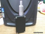
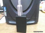
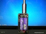
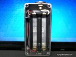
Here is the final product. It works great. Right now I have a .40 build using 24 AWG Kanthal in the Little Boy RDA and it hits like a champ.
 

Attachments

  • Closed.JPG
    Closed.JPG
    37.6 KB · Views: 83
  • open.JPG
    open.JPG
    45.3 KB · Views: 126

d00hickey

Member For 4 Years
Member For 3 Years
Member For 2 Years
Member For 1 Year
Member For 5 Years
Cool, looks good man. Love seeing homemade box mod projects.
Thanks, I wouldn't have been able to build it without your help. I've built a couple of DNA boxes that were really easy but this was the first mod I've built from scratch. I learned a ton, I like the mod, and I'm already thinking about what I want to build next.
 

Wabah58

Silver Contributor
Member For 4 Years
Thanks, I wouldn't have been able to build it without your help. I've built a couple of DNA boxes that were really easy but this was the first mod I've built from scratch. I learned a ton, I like the mod, and I'm already thinking about what I want to build next.
It is kind of cool when it's done and working :)
I have a few projects in the future, think the next one might be a dna 30 in a special box, might be asking for advice.LOL
 

d00hickey

Member For 4 Years
Member For 3 Years
Member For 2 Years
Member For 1 Year
Member For 5 Years
There is a 35watt Vamo chip out there that looks like it would make for an easy build. All the buttons and screen are built into the chip so there is just a negative and positive point to solder to. It wouldn't have much customization but I imagine it would fit well into any enclosure you could think of.
 

Wabah58

Silver Contributor
Member For 4 Years
There is a 35watt Vamo chip out there that looks like it would make for an easy build. All the buttons and screen are built into the chip so there is just a negative and positive point to solder to. It wouldn't have much customization but I imagine it would fit well into any enclosure you could think of.
Link? I have the cheap dna 30 on way from FT, should be here by Christmas :)
 

d00hickey

Member For 4 Years
Member For 3 Years
Member For 2 Years
Member For 1 Year
Member For 5 Years
Link? I have the cheap dna 30 on way from FT, should be here by Christmas :)

I've been trying to find it without success. I found it through a post on either Vaporjoes or Gotsmok about a special on RDAs. I recal it being slightly more expensive than the 35w Vamo on Fasttech so it would be cheaper to take one of those apart.

it was a lot like the chips from Yihiecigar. It was like an SX330 or SX350 with a Vamo button layout.

http://www.yihiecigar.com/products_info/YiHiEcigar-SX330-V2-S-60W-277372.html
 
Last edited:

Wabah58

Silver Contributor
Member For 4 Years
I've been trying to find it without success. I found it through a post on either Vaporjoes or Gotsmok about a special on RDAs. I recal it being slightly more expensive than the 35w Vamo on Fasttech so it would be cheaper to take one of those apart.

it was a lot like the chips from Yihiecigar. It was like an SX330 or SX350 with a Vamo button layout.

http://www.yihiecigar.com/products_info/YiHiEcigar-SX330-V2-S-60W-277372.html

Im in a sx350 group and the website they all use dont have the smaller chips.Even the 50 watt chip is high :(

http://www.varitube.com/Authentic-YiHi-SX350-50W-Chip_p_130.html

http://vaposphere-usa.com/collections/mods-1
 

VU Sponsors

Top