Become a Patron!

Mosfets

tomkp

Member For 4 Years
Hello everyone,

I'm new to making my own box mod and my question is, in the videos that I've watched some people are piggybacking 2 mosfets and some aren't, why is that? It doesn't matter if it's on a parallel or series mod, I've seen it on both. And what are the different mosfets that can be used? So far I've only seen the irlb3034. Thanx

Sent from my SAMSUNG-SM-G870A using Tapatalk
 

DIY FancyLights

Member For 4 Years
From the technical point of view, putting two MOSFET's in parallel (aka piggybacking) reduces the resistance & heat allowing for improving battery life & higher wattage builds. The difference is more noticeable in parallel builds then series because of the voltage differences, but it does affect both of them. The higher the wattage involved, the more important it is to worry about every single mOhm including the wiring and MOSFET's

Some of the more common MOSFET's to use are the IRLB3034, IRLB3813, and the PSMN1R9-40PLQ. I'm also getting increased sales on my PSMN0R9-25 based microFET board in eBay that has lower resistance then those other MOSFET's and can be put into parallel just by stacking them up and running the wires through both sets of holes (the MOSFET & pulldown resistor are already soldered to the board).

There are other MOSFET's that can work, but many that won't. They need to be selected based at a minimum on there Vgs(th) (turn on voltage), Rds(on) (On Resistance) at the voltage of your batteries, Id (continuous current), along with making sure the Vdss (max voltage) is higher then the batteries could possibly reach. After that, the style of case, cost, availability & other factors start coming into play. For example the PSMN0R9-25 MOSFET is a 'better' MOSFET then the other three, but the surface mount case is a pain for most modders to use, which is why the other three have been more popular.

DISCLAIMER:
I don't personally vape or build mods myself, but have a lot of technical experience with electronics and have gotten involved in the community here from helping modders out. That's what led to building the microFET boards to supply a 'better' part in a small space at reasonable costs. I welcome any correction from actual modders based on RL experience with your builds.
 

Mike H.

Gold Contributor
Member For 4 Years
Member For 3 Years
Member For 2 Years
*Raises hand...i have a question...How does one go about testing the maximum capable amperage of a mosfet ,with no numbers to reference and research?
 

DIY FancyLights

Member For 4 Years
Without a part number to lookup the information in datasheets it ends up being beyond that capabilities of most normal users. It involves attaching the MOSFET to a massive heatsink, measuring the current & temperature and increasing the current load until either a critical temperature is reached or the part blows/fails. With many high current MOSFET's, the actual leads or case can fail before the silicon inside does (the IRLB3034 for example states a lower current limit because of the package then what the actual MOSFET inside can handle).

For box mods, since the MOSFET's aren't attached to heatsinks and you don't want a lot of heat inside your case near the batteries, the actual current you can run safely through the MOSFET is actually lower then the max rated current. This is part of the reason you want very low Rds(on) resistance so you generate less heat at your currents. Knowing a MSOFET can handle high currents and has a low Rds(on) resistance help combine to know how well it can work in a box mod without going through additional work better left to engineers.
 

Mike H.

Gold Contributor
Member For 4 Years
Member For 3 Years
Member For 2 Years
Low Rds being that of an N mosfet which we typically use in box mods.

Quite a bit off topic but, I was asking as im trying to determine what the max amperage capabilities are in some flight control board mosfets to make comparisons..I asked a fellow forum member on a different type of site about a particular board and was told it used 3.5 amp mosfets but, im not sure how he knows with no reference numbers to look this up...I thought maybe an easy way to determine this...Now im bummed out...lol
 

DIY FancyLights

Member For 4 Years
Could it be 3.5A is what they are running through the MOSFET not what they are actually rated at? It's also possible that information was passed on form other people, including some that may have had the actual information.

Also for most short turn on time applications, you can estimate an approximate max current based on the Rds(on) & Voltage applied to calculate a current for your actual application. That will give you the max theoretical current do to limitations in the chip without taking into account the MOSFET heating up to destruction. The reason this can give you a close figure for MOSFET's on only a short time is that heat buildup is one of the things that causes failure and a MOSFET that's Off longer then it is on has more time to cool off. The Rds(on) you can safely measure without damaging the MOSFET, the measured value with a multimeter can give you a starting point, but a better way to measure that is under load and measuring the current and voltage drop because the resistance can vary based on voltage and load also.
 

DIY FancyLights

Member For 4 Years
P.S. For looking at a parts Rds(on) for box mod vapes, I usually look at the rated Rds(on) value @ 4.5V as well as the graphs for the proper voltages (3.7V parallel, 7.4V for 2S). The quick Rds(on) listed in general is actually at 10V, and there are parts that look good until you check their values at the proper Gate voltages. That's part of the reason to do a quick check of the turn on voltage Vgs(th) to make sure it is well below the voltage applied before even looking at the Rds(on) charts. Having a description of Logical Level or sub-logic level also helps spot a lower Vgs(th)

Some of the high current MOSFET some people have asked about using in the past that were told no was because they wouldn't operate at the required voltages.

Now I'm just rambling :)
 

Mike H.

Gold Contributor
Member For 4 Years
Member For 3 Years
Member For 2 Years
3.5 amps would be the maximum load capacity...The flight control boards of interest use 3.7v 1s lipo batteries to power 4 or more 6mm, 7mm or, 8.5mm micro motors.

Many variable such as weight to lift and prop size or even gearing in some cases (direct drive , in others) change the load..So my interest is in finding out what a selected boards mosfet (for the Electronic speed controller portion) can handle before burning one up...Im referring to boards with built in Electronic speed controllers in which no specifications are given for the mosfets capabilities...we dont get separate speed controllers that would advertise them to be 10 amps or 20amps etc.., like some.
 
Last edited:

DIY FancyLights

Member For 4 Years
I think the MOSFET's used can handle a more then 3.5A or the Rds(on) starts getting too high and you have too much of a voltage drop which then affects the motors. For 3.7V @3.5A that's about 13W and about 1 Ohm, so you need an Rds(on) or 0.1 Ohm (100mOhm) or preferably lower. Even at 0.1 ohm that means a 10% loss of power in the MOSFET! So, I strongly expect what's being used is lower then that.

If I was designing the circuit I'd want 20mOhm or less myself, and those parts are usually rated at 7A or higher and cost around $0.20 each in bulk. But then again they may have gone with 5A parts with higher resistance because of the $0.09 type price. But keep in mind that the current the MOSFET can handle also depends on how it's mounted, including how much copper is near the MOSFET to help draw off heat. their ratings are usually with a certain amount of copper or a huge heatsink depending on the type of MOASFET.

Choosing parts sometimes takes you to less desirable parts just to lower the cost a few cents.
 

tomkp

Member For 4 Years
So in the application of a box mod, I'm guessing that on a parallel build you want the lowest voltage drop through the mosfet? You are a bit above me on hoe to calculate that.

Sent from my SAMSUNG-SM-G870A using Tapatalk
 

DIY FancyLights

Member For 4 Years
For most people here, I simply suggest to use MOSFET's already being used in single MOSFET's builds for any parallel builds. All the MOSFET's I've seen recommended here will work well for either Parallel or Series batteries.

I was going off into tangents about factors involved in selecting the MOSFET's which why certain MOSFET's are preferred for those that are interested in the information. Since I don't actually build boxes myself, that type of information will help others that have done MOSFET selection in the past know what I'm talking about.
 

tomkp

Member For 4 Years
For most people here, I simply suggest to use MOSFET's already being used in single MOSFET's builds for any parallel builds. All the MOSFET's I've seen recommended here will work well for either Parallel or Series batteries.

I was going off into tangents about factors involved in selecting the MOSFET's which why certain MOSFET's are preferred for those that are interested in the information. Since I don't actually build boxes myself, that type of information will help others that have done MOSFET selection in the past know what I'm talking about.
So you can use the same mosfet for either a parallel or series build?

Sent from my SAMSUNG-SM-G870A using Tapatalk
 

DIY FancyLights

Member For 4 Years
Yes, in general any MOSFET for Parallel batteries will work for Series battery builds as well unless you go an outrageous number of Volts (like > 20V). The same MOSFET's can also be used in parallel with each other for people wanting that (usually high wattage builds?).

One more recommendation. Anytime you parallel MOSFET's I do recommend the both be of the same type. I don't think it's required, just good practice so both turn on to the same amount at the same time.
 

tomkp

Member For 4 Years
Yes I was trying to decide if I was going to use two mosfets in parallel as well. The box I'm making is going to be a switch box so I can go parallel to series on the fly depending on the coil I build. I know that if you put two mosfets in parallel it halves the load to each

Sent from my SAMSUNG-SM-G870A using Tapatalk
 

CurlyxCracker

Gold Contributor
Member For 4 Years
Member For 3 Years
Member For 2 Years
Member For 1 Year
Member For 5 Years
Yes I was trying to decide if I was going to use two mosfets in parallel as well. The box I'm making is going to be a switch box so I can go parallel to series on the fly depending on the coil I build. I know that if you put two mosfets in parallel it halves the load to each

Sent from my SAMSUNG-SM-G870A using Tapatalk
I recommend @DIY FancyLights "microfet" on eBay. Put it in my series box. Works wonderful, easy as hell to solder.
 

tomkp

Member For 4 Years
Kewl. I have the 3034 coming and already have the 15k resistor. But ima keep this in mind for my next one

Sent from my SAMSUNG-SM-G870A using Tapatalk
 

tomkp

Member For 4 Years
Almost complete. First build. Dual unregulated parallel/series switch box with voltmeter. It will have a master on/off switch and a switch to choose voltmeter constant on or on with fire button

Sent from my SAMSUNG-SM-G870A using Tapatalk
 

CurlyxCracker

Gold Contributor
Member For 4 Years
Member For 3 Years
Member For 2 Years
Member For 1 Year
Member For 5 Years
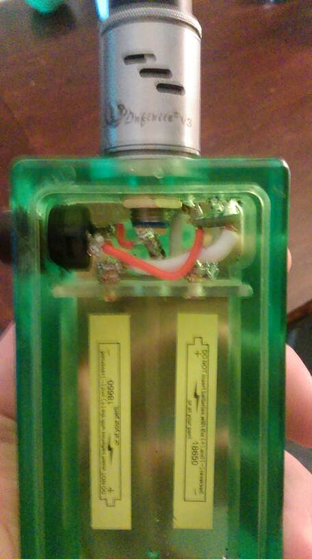
This is mine before I heatshrinked it up with a microfet.
39288b72bb4bb50080bd3720d3fc30ad.jpg
 

tomkp

Member For 4 Years
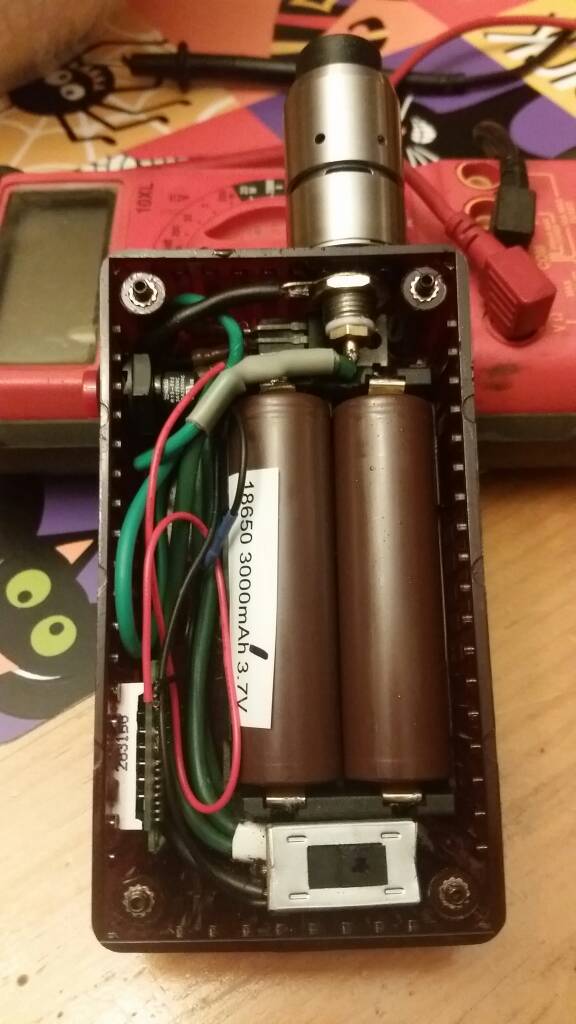
01f20d83d2fa2052ac91458fb816d898.jpg


Here my product almost finished. Switch box, dual mosfet, fuse, voltmeter. Will be adding master on/off and a switch to turn on the voltmeter on without hitting the fire button and a led halo fire switch

Sent from my SAMSUNG-SM-G870A using Tapatalk
 
Last edited:

tomkp

Member For 4 Years
I have a .54 dual coil and when vaping it, my voltmeter shows 7.25v. Is that the power left in the batteries, or the power that I am using?

Sent from my SAMSUNG-SM-G870A using Tapatalk
 

VU Sponsors

Top