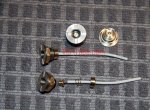
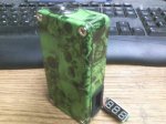
Main Part List:
Fatdaddy V4 22mm
18650 SLED
Hammond 1590BBK
International Rectifier 3034 Mosfet
15k 1/4w Resistor
A Random Button I had Because I ordered the wrong one
*Amazon links used to aid in longevity of link success in future
First and foremost, remember when building anything that it will blow up and you will die. Since 90% of these threads say that I wanted to just knock it out now so we can have fun and no one bothers us. Remember Charles Darwins theory of survival of the fittest? It applies to us too so do some research or blame no one but yourself on your extinction.
Great, now that that is covered let us begin!
Realistically my main goal for going more volts was so i can reduce amp output yet yield high watt results and maintain efficiency along the way and eventually fix form factor. I started with 18650 batteries because my other "subjects" have not arrived yet. This thread will be updated with the new projects.
The Hammond box is wayyyy overkill for size but I just wanted plenty of room to work with on my initial test one. Sorry if she fugly. I got side tracked and had to redo the entire build from my lack of focus.
A side note for wiring. I used 14 gauge (32 amps) stranded wire on the Positive to the 510 connector, the bottom of the SLED and then the rest I ran 18 gauge (16 amps) solid wire since whatever coming from MOSFET gets regulated. Next time I'll just use 18 gauge & 20 gauge (11 amps) to save space and be real.
ooooops didnt take 510 soldering pic...
Get your diagram knocked out for reference

Drill Some Holes to fit button and head then check fitment


Get the Mosfet Ready. Resistor gets put on Gate & Source legs.

Get that button ready (id do this ish last next time lol)

Get Sled Ready - This is SERIES so the - & + of the battery are sharing the bottom

This part of the Fatdaddy goes to the DRAIN leg

Set everything up like a failure. There was no reason for me to be sloppy and do it like that

Innards of the self destructing box - ghetto batteries cuz i live life on the ledge

Coils! This one I just slapped together a .53 ohm build. 24 Gauge 9 wraps on a 4.0mm sized "bit"

Checkin Ohms (thats how i knew it was .53 sukka)

Verify smoke with Cotton

Verify wattage & Amps - For reference a 3.7v build would require OHMS of .14 @ 28 amps. pfft what a waste

Cute

Heres a prelim video
I was bummed, it didnt explode. Everything worked like a charm and it hits like a champ. Realistically I want to settle between 80-90w, I feel at 100w its just a little to hot for me (im not a smoker). I have no taste buds so I barely ever vape for taste, more cloud play but this is definitely tasty still. Will make a .65 ohm (85w @ 12 amp) tomorrow.
Thats it. Like I said I will update with new builds and enhancements. Feel free to dump questions, theories and ideas in this thread. If you arent going to add something of value, please just watch the thread from sidelines. Safety concerns have been met to my minimum standards.
Fatdaddy V4 22mm
18650 SLED
Hammond 1590BBK
International Rectifier 3034 Mosfet
15k 1/4w Resistor
A Random Button I had Because I ordered the wrong one
*Amazon links used to aid in longevity of link success in future
First and foremost, remember when building anything that it will blow up and you will die. Since 90% of these threads say that I wanted to just knock it out now so we can have fun and no one bothers us. Remember Charles Darwins theory of survival of the fittest? It applies to us too so do some research or blame no one but yourself on your extinction.
Great, now that that is covered let us begin!
Realistically my main goal for going more volts was so i can reduce amp output yet yield high watt results and maintain efficiency along the way and eventually fix form factor. I started with 18650 batteries because my other "subjects" have not arrived yet. This thread will be updated with the new projects.
The Hammond box is wayyyy overkill for size but I just wanted plenty of room to work with on my initial test one. Sorry if she fugly. I got side tracked and had to redo the entire build from my lack of focus.
A side note for wiring. I used 14 gauge (32 amps) stranded wire on the Positive to the 510 connector, the bottom of the SLED and then the rest I ran 18 gauge (16 amps) solid wire since whatever coming from MOSFET gets regulated. Next time I'll just use 18 gauge & 20 gauge (11 amps) to save space and be real.
ooooops didnt take 510 soldering pic...
Get your diagram knocked out for reference

Drill Some Holes to fit button and head then check fitment


Get the Mosfet Ready. Resistor gets put on Gate & Source legs.

Get that button ready (id do this ish last next time lol)

Get Sled Ready - This is SERIES so the - & + of the battery are sharing the bottom

This part of the Fatdaddy goes to the DRAIN leg

Set everything up like a failure. There was no reason for me to be sloppy and do it like that

Innards of the self destructing box - ghetto batteries cuz i live life on the ledge

Coils! This one I just slapped together a .53 ohm build. 24 Gauge 9 wraps on a 4.0mm sized "bit"

Checkin Ohms (thats how i knew it was .53 sukka)

Verify smoke with Cotton

Verify wattage & Amps - For reference a 3.7v build would require OHMS of .14 @ 28 amps. pfft what a waste

Cute

Heres a prelim video
I was bummed, it didnt explode. Everything worked like a charm and it hits like a champ. Realistically I want to settle between 80-90w, I feel at 100w its just a little to hot for me (im not a smoker). I have no taste buds so I barely ever vape for taste, more cloud play but this is definitely tasty still. Will make a .65 ohm (85w @ 12 amp) tomorrow.
Thats it. Like I said I will update with new builds and enhancements. Feel free to dump questions, theories and ideas in this thread. If you arent going to add something of value, please just watch the thread from sidelines. Safety concerns have been met to my minimum standards.
Last edited:


