Become a Patron!

Switch confusion

Daniel

Silver Contributor
Member For 4 Years
Member For 3 Years
Member For 2 Years
I have a question I want to run by you all & get some opinions or suggestions. I am in the process of building a wooden box mod for myself, & was checking on some options. I'm doing the woodwork only, the wiring up will be done by a more qualified builder.

My question & confusion is in the area of switches, a mosfet vs. a 16-600 resettable fuse. I was told that the mosfet only protects the switch, & bypasses the current going through it, whereas the 16-600 protects the user. If too much current is going through the switch, the fuse trips & throttles down the current.

Maybe I am looking at this wrong, but I would think that protecting the user is paramount to anything else. I always use dual builds, w/ 26 or 24 gauge Kanthal, & I never go below .35 on my builds. Never. I'm just too nervous about super, sub low builds. So, could someone clue me in to which one is THE best one to use? I would be really grateful for any advice or suggestions.
 

Wabah58

Silver Contributor
Member For 4 Years
You are right the mosfet takes the amp load off the switch, where the fuses really come into play is for protection from shorts. Like putting a battery in the wrong way, or piece of kenthal gets in box and hits hot wire, those instances will trip the fuse.

My suggestion is always do the mosfet, and if you want protection from shorts go fuses too. That would be super safe.
 

BoomStick

Gold Contributor
Member For 5 Years
MOSFET definately, fuse if you want. The fet will keep the switch from welding itself together so it actually protects the switch and the user. Both components would definately be best. Good luck on the build.
 

MD_Boater

Silver Contributor
Member For 4 Years
I'm not a mod builder, but I have a degree in electronics. Use both for the reasons that you listed.

This is not a MOSFET vs fuse thing. This is a MOSFET and a fuse thing. You should absolutely use both.

The MOSFET uses a lower voltage and current side to activate a higher current load circuit. The fuse protects the high current load.

If you just wired a switch inline with your battery and coil, it will have to pass through all of that current going to the coil every time. Your batteries are pretty strong. This high current will cause a little spark across the switch contacts just before they touch every single time that you hit the button. Think mini spot welder. Eventually, your nice, smooth clean contacts look like the surface of the moon. You end up with a bunch of little craters not making contact, and therefore less electricity can flow through it. It also reduces the amount of current that can cross the connection to get to the coil. The MOSFET allows the switch to use a lower, safer, current to control the higher current going to the actual load.

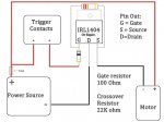
With the MOSFET wired in, when you press the switch, it sends a lower voltage to the "G" pin on the MOSFET. This is the "Gate". When the Gate is activated (voltage supplied to it), it will allow current to flow from the "S" (Source) through the "D" (Drain) and back to the battery.

Your load circuit wiring should go from the + side of battery through the fuse (wire it in as close to the + side of the battery as possible so that it can protect as much of the circuit beyond it as possible) and then to the center (+) pin of your atomizer connector. The - connection from the connector should go to the "S" on the MOSFET, and the "D" side of the MOSFET goes back to the - side of the battery.

Below is a really nice diagram. Replace "motor" with "coil" and "trigger" with "switch". Since a motor is just a coil with a lot more windings, this diagram could actually be used to build a mod IF you add the fuse into the + side wiring from the motor. I'm sure that the MOSFET you have in mind has different ratings. Do NOT use a IRL1404 because it is in this picture posted here. I have NOT checked the specs on it. The switch completes the circuit from the + side of the battery (remember, the motor is just a coil, current will flow through it) through the 2 resistors to ground. The gate connects between the crossover resistor and the gate resistor, so it only uses part of the battery voltage to activate it. If you use an example 3.6V battery at full charge, the current would be approximately .163 milliamps through the resistor network and switch (very safe to handle, and won't weld or arc the switch).

On the coil side, a .5 ohm coil will allow a 3.6v battery to push up to 7.2A through it (real amps - nothing to laugh at - it will weld, burn, get ugly if uncontrolled). If you wired the switch into this circuit, it might even weld itself closed once you fired it. The internal resistance of the MOSFET will decrease the current slightly, and the switch / resistor network will make some current bypass the MOSFET, so the 7.2A is likely to be a little less in reality.
Edited to show fuse location...

mosfet-diag.jpg
 
Last edited:

VU Sponsors

Top