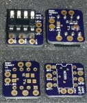
The Different Types of PWM Circuits
There are several simple types of PWM circuits most likely to be seen with vapes, from simplest to most complex:
1. The basic 555 timer
This is the simplest versions straight from basic 555 timer circuits.
Pros: Cheap, usually all through hole parts for easy assembly
Cons: Selection of which 555 timer chip is important to avoid your MOSFET blowing it, even the best ones still blow, so the 555 is usually socketed for easy replacement. Medium parts count
Battery info: 2S to 4S typical
Note: Many designs place the diodes at the external pot, this is both a pro & a con depending on your point of view.
2. PFET protected 555 timer
This adds a PFET & pull-up resistor to the basic 555 timer in order to protect the 555 timer from the current surges to the MOSFET which are the most common cause of failure.
Pros: still a simple design, PFET is usual a small SMD part to reduce the PCB increase
Cons: Reports the 555 can still fail, but much rarer. Higher parts count then a basic 555
Battery info: 2S to 4S typical
Note: Many designs place the diodes at the external pot, this is both a pro & a con depending on your point of view.
3. PFET protected mic1557 Timer
This is a recent variation on the PFET protected 555 taking advantage of a relative to the 555 timer that needs fewer parts for PWM and a smaller timer chip.
Pros: small footprint, fewer parts, on board BAT54S diode to simplify external wiring
Cons: new design, slightly higher timer cost, all SMD parts may discourage some people from doing it themselves (assembled from david4500 fixes this)
Battery info: 2S to 4S typical
4. Timer chip with Low Side MOSFET driver
Haven't seen this available yet, but it's the next step up in progression. Instead of just using a PFET buffer, a low side MOSFET driver chip is use to provide faster switching of the power MOSFET in both directions. The MOSFET pull-down then becomes a safety feature, not a required part for proper PWM operation and is usually a much higher value to improve the switch times.
Pros: Faster MOSFET on/off for cooler operations at high frequencies
Cons: higher cost, slightly larger PCB
Battery Info: 2S to 4S typical
Note: 2P to 4P could be possible with the proper MOSFET driver & power MOSFET combination
5. Timer chip with High Side MOSFET driver, used Low Side
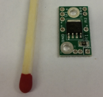
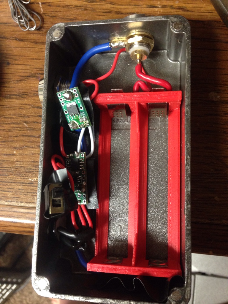
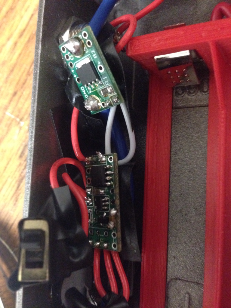
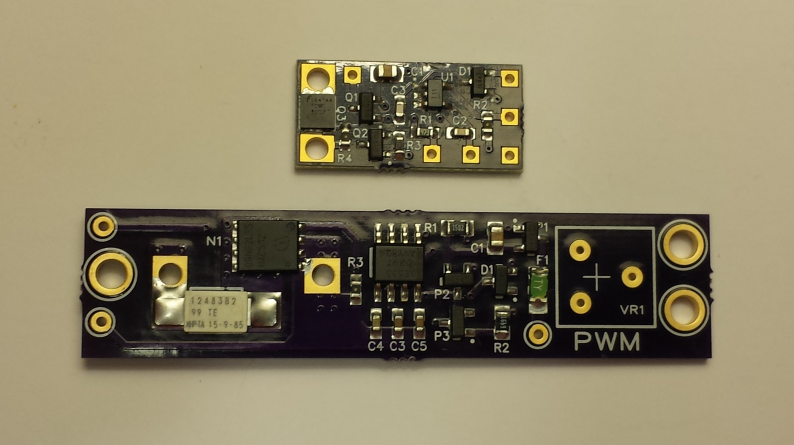
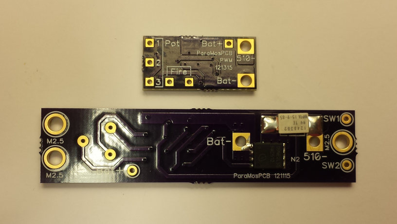
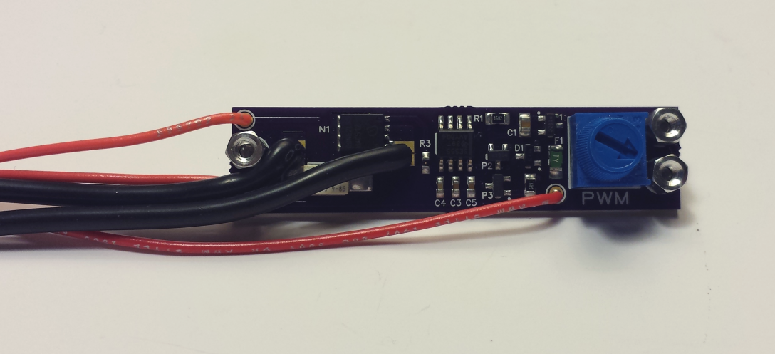
This uses a more complex high side MOSFET driver which also can boost the voltage, allowing for lower voltage requirements. This is the design my microPWM board uses that help start this thread. Most designs doing this will have the voltage limiting in the chip, but some version people build may need an external zener
Pros: lower minimum voltage, voltage booster improves power MOSFET performance (specially at 2S and lower frequency 2P to 4P)
Cons: higher cost, low voltages requires low frequency, larger PCB
Batter Info: 2P to 4S, 2P to 4P requires lower frequencies
Note: the microPWM design keeps part count & PCB size down at the expensive of requiring lower frequencies for low voltages. The solution to this is closer to the next one listed below
6. Timer chip with High Side MOSFET driver used High Side
This version uses a more complex high side driver, but allows your power MOSFET to be used between the battery + and the vape. Optionally, it could be downgraded to being used with a standard low side if the proper voltage limiting is on chip or a zener diode is in place. A big difference form the previous versions is more parts and the driver is usually more expensive, but it improves the driving at low voltages
Pros: better performance at all voltages
Cons: More complex, higher cost, people more familiar with low side, additional feedback wire needed from high side MOSFET
Battery info: 2S to 4S typical, 2P to 4P with a more complex versions requiring more expensive parts
7. MCU with various output drivers
Included more for completeness, most regulated designs that are smart are MCU based instead of timer based, but outside of the intended scope of this thread. They often have feedback for how much power is being used and/or temp sensors, and you program them for how you want to work.
Pros: smarter, more options, often driving a display, uses feedback to better regulate the output
Cons: very complex, highest cost, MCU programming required, an error can cause very unexpected results
Battery info: 2S to 4S typical, 2P to 4P possible (but do those exist yet)
I have skipped over some possible designs including ones that could use different circuits to generate the PWM signal since most people will end up opting for 555, mic1557,por similar chips because it makes the design simpler or they end up jumping to an MCU design.
Are there others that you have seen or been considering building that should be mentioned?


