Become a Patron!

How-To & Why-To of PWM box mods

DIY FancyLights

Member For 4 Years
This thread is an attempt to pull together information related to PWM box mobs that's already out there and scattered and to allow for conversations, suggestions, links, help etc related to simple PWM box mod vapes. This is started as a spin off from the Basic MOSFET wiring so that thread can stick to simpler subjects while we delve more into more complex PWM design while avoiding the highly regulated and high end designs.

I'll start this of by say that a PWM vape is the simplest of the regulated type vapes that allows you to adjust how much power goes to your coil. While it's nice to be able to fine tune it does have it's disadvantages such as it may need adjusting as your batteries drop and any time you change your coil. But, it is the simplest design that lets you easily adjust the power you're using for vaping and can extend the life of your batter charge since it doesn't run the vape coil constantly

Everyone please add you hints information link etc to help people wanting to or thinking about a PWM vape!

... more to follow ...
 

Soupnazi

Member For 4 Years
Member For 3 Years
Member For 2 Years
Member For 1 Year
Member For 5 Years
I guess we will assume you want to start selling PWM boards? Let's just hope they are a better design than the boards to mount a fucking mosfet on. LMAO. How about posting just 1 box that you have built and vaped on with your stuff so we can see what you got, and no B boxes.

Untill then, guess I'll keep visiting the dumb guys, basic stuff, on the basic mosfet thread, atleast them guys build.
 
Last edited:

DIY FancyLights

Member For 4 Years
While it's true that I don't personally vape and build mods myself as I've said elsewhere, I bring in technical experience as a trained technician who has worked on a wide variety equipment and trained on even more (including being trained on a 300A switching power supply). I don't vape or try it myself because I did quit smoking a long time ago so can at least sympathizes with peoples needs here and was brought here by people I was giving technical help to. This thread is intended to become a logical extension of the Basic MOSFET thread that everyone should add to.
 

krashkrieg

Bronze Contributor
Member For 4 Years
Thank you! I for one look forward to the knowledge to be gained from this thread.
I want to build one as my next box.
I'm great with my hands, soldering and keeping it all neat, just don't know diddly about PWM or any calculations/ others parts needed.
 

DIY FancyLights

Member For 4 Years
Basic PWM Theory

First a little bit of the basics ... PWM works by repeatedly turning power off & on at the desired rate so that the average power can be a specific % of the available power. For PWM vapes that means if you have 8V batteries running with 50%, how have an average of 4V, 75% would be an average of 6V. By adjusting the on/off ratio up or down you can get almost any effective power. You just have to remember that the batteries and switch (usually a MOSFET for vapes) needs to be able to handle the maximum current of 100%

How fast you do the pulses makes a difference once you get practical. High speed pulses make the average smoother, but ,most high current MOSFET's can have limits to how fast they can switch. On top of that, the more often the MOSFET switches the hotter it will get because while it is turning off or on is when most of the heat is generated in PWM circuits. Another factor that comes up is that PWM vapes can make noise, from a low buzz to a high pitch whine that can irritate people. That means that personal preferences are also factors in PWM frequency.

Finally there are additional technical issues in specific designs caused by specifications and voltages involved that become additional factors, for example the lower the voltages you are working with the slower you should switch the MOSFET off & on to reduce heating because the parts take longer to turn off & on at lower voltages.

Most simple PWM systems used with vapes will have a simple adjustable resistor you change to set what the on/off percentage in. It can be a pot on or through the case or a more precises multi turn trimpot. There are advantages and disadvantages to both types of pots. Since the PWM's power is based on % of the voltage, as your batteries drop, you may find yourself adjusting the PWM, and you definitely will want to adjust it each time you change the vape coil(s).

Final note: many more complex regulated mods at their core still use PWM to control the power going to the coils. Their difference really is in how the PWM is controlled more automatically by taking into account the battery levels or the actual temperature of the coil. Often those are using computers to intelligently adjust the PWM signal to give you the desired power.

more to follow ...
 

VapeTechnologies

VapeTechnologies LLC Advanced Custom Boxes
VU Donator
Member For 4 Years
Member For 3 Years
Member For 2 Years
Unlisted Vendor
@Soupnazi made me LOL... dumb MOSFET guys.

Ok so I just received some awesome #vapemail courtesy of @DIY FancyLights and I'm really looking forward to digging into this. I'm backed up with 3 custom orders due by Friday and a semi-custom batch of 10 Raptor boxes that the shop would like to have before Christmas, so I won't be able to start this until next week at the least. But here's some pics and I'll be back to this thread for a build log using DIY fancylights micro PWM PCB boards.

The black PWM board pictured in one of the photos is for comparison. They are the ModPCB boards I am currently using and populating myself. DIYfancylights design is the "green" PCB board shown in photos, along with all the nicely packaged SMD and through-hole components, sealed in anti-static packets.

MICRO_PWM (1).jpg MICRO_PWM (4).jpg MICRO_PWM (5).jpg MICRO_PWM (7).jpg MICRO_PWM (8).jpg MICRO_PWM (9).jpg MICRO_PWM (11).jpg Untitled.png MICRO_PWM (16).jpg
 

DIY FancyLights

Member For 4 Years
The Different Types of PWM Circuits

There are several simple types of PWM circuits most likely to be seen with vapes, from simplest to most complex:

1. The basic 555 timer
This is the simplest versions straight from basic 555 timer circuits.

Pros: Cheap, usually all through hole parts for easy assembly
Cons: Selection of which 555 timer chip is important to avoid your MOSFET blowing it, even the best ones still blow, so the 555 is usually socketed for easy replacement. Medium parts count
Battery info: 2S to 4S typical
Note: Many designs place the diodes at the external pot, this is both a pro & a con depending on your point of view.

2. PFET protected 555 timer
This adds a PFET & pull-up resistor to the basic 555 timer in order to protect the 555 timer from the current surges to the MOSFET which are the most common cause of failure.

Pros: still a simple design, PFET is usual a small SMD part to reduce the PCB increase
Cons: Reports the 555 can still fail, but much rarer. Higher parts count then a basic 555
Battery info: 2S to 4S typical
Note: Many designs place the diodes at the external pot, this is both a pro & a con depending on your point of view.

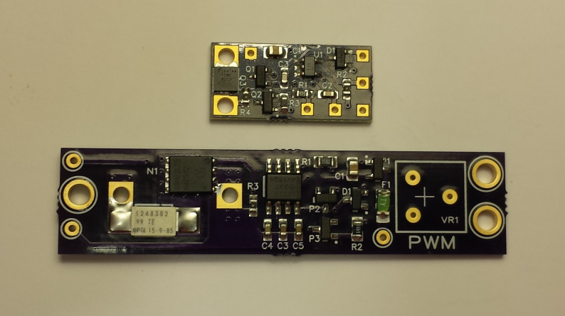
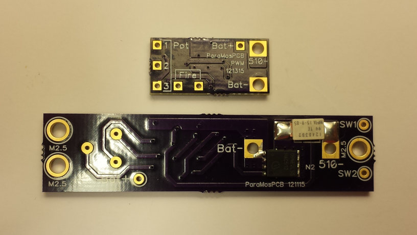
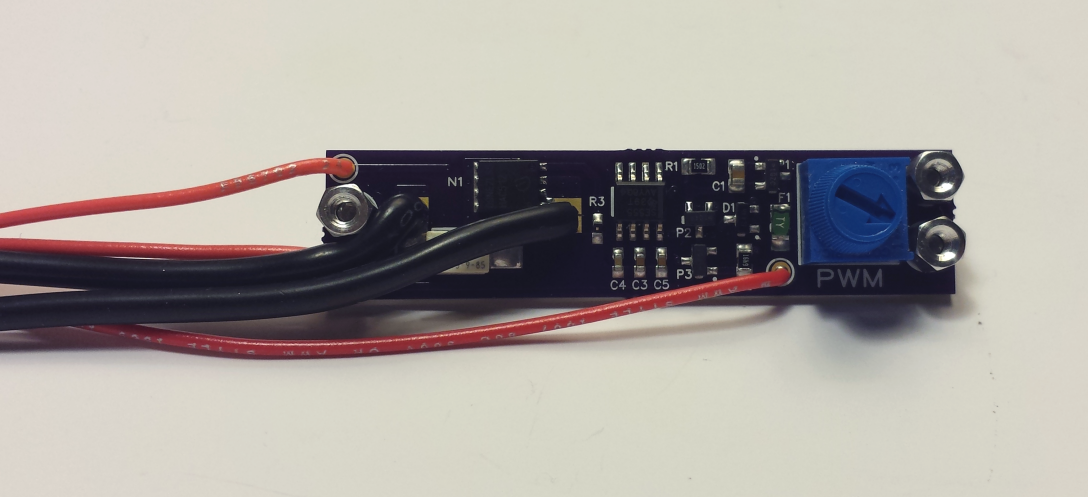
3. PFET protected mic1557 Timer
This is a recent variation on the PFET protected 555 taking advantage of a relative to the 555 timer that needs fewer parts for PWM and a smaller timer chip.

Pros: small footprint, fewer parts, on board BAT54S diode to simplify external wiring
Cons: new design, slightly higher timer cost, all SMD parts may discourage some people from doing it themselves (assembled from david4500 fixes this)
Battery info: 2S to 4S typical

4. Timer chip with Low Side MOSFET driver
Haven't seen this available yet, but it's the next step up in progression. Instead of just using a PFET buffer, a low side MOSFET driver chip is use to provide faster switching of the power MOSFET in both directions. The MOSFET pull-down then becomes a safety feature, not a required part for proper PWM operation and is usually a much higher value to improve the switch times.

Pros: Faster MOSFET on/off for cooler operations at high frequencies
Cons: higher cost, slightly larger PCB
Battery Info: 2S to 4S typical
Note: 2P to 4P could be possible with the proper MOSFET driver & power MOSFET combination

5. Timer chip with High Side MOSFET driver, used Low Side
This uses a more complex high side MOSFET driver which also can boost the voltage, allowing for lower voltage requirements. This is the design my microPWM board uses that help start this thread. Most designs doing this will have the voltage limiting in the chip, but some version people build may need an external zener

Pros: lower minimum voltage, voltage booster improves power MOSFET performance (specially at 2S and lower frequency 2P to 4P)
Cons: higher cost, low voltages requires low frequency, larger PCB
Batter Info: 2P to 4S, 2P to 4P requires lower frequencies
Note: the microPWM design keeps part count & PCB size down at the expensive of requiring lower frequencies for low voltages. The solution to this is closer to the next one listed below

6. Timer chip with High Side MOSFET driver used High Side
This version uses a more complex high side driver, but allows your power MOSFET to be used between the battery + and the vape. Optionally, it could be downgraded to being used with a standard low side if the proper voltage limiting is on chip or a zener diode is in place. A big difference form the previous versions is more parts and the driver is usually more expensive, but it improves the driving at low voltages

Pros: better performance at all voltages
Cons: More complex, higher cost, people more familiar with low side, additional feedback wire needed from high side MOSFET
Battery info: 2S to 4S typical, 2P to 4P with a more complex versions requiring more expensive parts

7. MCU with various output drivers
Included more for completeness, most regulated designs that are smart are MCU based instead of timer based, but outside of the intended scope of this thread. They often have feedback for how much power is being used and/or temp sensors, and you program them for how you want to work.

Pros: smarter, more options, often driving a display, uses feedback to better regulate the output
Cons: very complex, highest cost, MCU programming required, an error can cause very unexpected results
Battery info: 2S to 4S typical, 2P to 4P possible (but do those exist yet)

I have skipped over some possible designs including ones that could use different circuits to generate the PWM signal since most people will end up opting for 555, mic1557,por similar chips because it makes the design simpler or they end up jumping to an MCU design.

Are there others that you have seen or been considering building that should be mentioned?
 

VapeTechnologies

VapeTechnologies LLC Advanced Custom Boxes
VU Donator
Member For 4 Years
Member For 3 Years
Member For 2 Years
Unlisted Vendor
Hey guys, just a quick update on the process. Just powder coated another batch of enclosures tonight so this micro PWM by DIY_fancylights should be getting a test drive real soon. So far so good, enjoyed populating the board (rework gun/hot air) and I'm really digging the on-board options for the master and pot. This board opens up a lot of possibilities with both 1590A and 1550P sized enclosures.
2_MICRO_PWM (3).jpg

Here's an unrelated 1550P box I just finished up, but I plan on using the same component placement with DIY's PWM board/FET

2_MICRO_PWM (1).jpg
Yes, got a little juice on my finger up there ;)

So if I do decide to put this board in a 1550P, here's the sled and "rough" placement of components....

2_MICRO_PWM (6).jpg

However, a 1590A box is also an option, and I powder coated 1590G, 1590G+, 1550P, and 1590A enclosures so I'm still deciding which one to pick for this build... The PWM/FET combo will fit nicely behind a 1590A battery sled, only problem is I like to SEE my work in boxes :)

This pic was taken before the enclosures were coated...

PWM (3).jpg

2_MICRO_PWM (5).jpg


Here's a few more pics of the board in it's "almost finished" glory... Here, you can see utilization of the on-board master ON/OFF switch, and on-board trimmer options... I'm really digging that, keeps things clean and looking good.

2_MICRO_PWM (4).jpg


If you couldn't tell already by my over exaggerated and continuous mentions of my powder coating job tonight, please just let me show off how sexy these girls came out after curing in the oven. The black is a Krekote ultra flat black firearm coating, and the pink in lazer polka dot pink by prizmatic, it "shimmers" and changes tones at different angles. Totally made my night the way these came out...
(DVM in pink box is just sitting in there, not attached yet, that's why it's crooked)

PWM (2).jpg

PWM (1).jpg
PWM (5).jpg
 

Attachments

  • 20151130_162747.jpg
    20151130_162747.jpg
    245.7 KB · Views: 116

krashkrieg

Bronze Contributor
Member For 4 Years
Your boxes are looking great !

Where can I by that on off switch and blue pot?

Sent from my shoe phone using Tapa Toe Pro
 

VapeTechnologies

VapeTechnologies LLC Advanced Custom Boxes
VU Donator
Member For 4 Years
Member For 3 Years
Member For 2 Years
Unlisted Vendor
Your boxes are looking great !

Where can I by that on off switch and blue pot?

Thanks,
You don't want to use those pots trust me. They are good if you have some kind of dimmable LED set up to tell you where your value is at, but otherwise they are not single turn, the dial with continually rotate right or left so it's impossible to know where you're at. I was using the pot for testing purposes but next set of photo's you'll see what type of pot I use regularly. Plus I was waiting to double check with @DIY FancyLights about proper mounting of my particular pot used before I soldered anything, so the blue pot was used during prototyping the circuit

Here's a few PCB's for fun!
PCB.jpg
 

DIY FancyLights

Member For 4 Years
I have the kits without pots available on eBay or you can purchase directly from me to get an additional discount without eBay fees. I can sell the PCB blanks as well, but the bulk buy I did for the parts will help you a lot more then buying them yourself.

Kit qty 1: http://cgi.ebay.com/ws/eBayISAPI.dll?ViewItem&item=252177685818
Kit qty 5: http://cgi.ebay.com/ws/eBayISAPI.dll?ViewItem&item=252177689400
Kit qty 10: http://cgi.ebay.com/ws/eBayISAPI.dll?ViewItem&item=252177690859

We also sell the microFET board he's using with the microPWM. That comes assembled with a low resistance PSMN0R9-25 MOSFET and a pull down resistor already installed, and space for a through hole resistor if you want to light an LED when it's on. Technically, that MOSFET is better then an IRLB3034 for vaping. They have lower resistance at the cost of lower voltage, and me having them assembled gets rid of the negative of being an SMD part.

microFET qty 1: http://cgi.ebay.com/ws/eBayISAPI.dll?ViewItem&item=261960134586
microFET qty 5: http://cgi.ebay.com/ws/eBayISAPI.dll?ViewItem&item=261960164740
microFET qty 10: http://cgi.ebay.com/ws/eBayISAPI.dll?ViewItem&item=252021007193
5 microFETs + 14awg wire + heatshrink assortment: http://cgi.ebay.com/ws/eBayISAPI.dll?ViewItem&item=252096055090

Important NOTE: the microPWM board requires a different pulldown resistor on the microFET board then we made them with. We do include that proper part to use with microFETs or standard MOSFETs with the microPWM kits.
 

DIY FancyLights

Member For 4 Years
Thanks,
You don't want to use those pots trust me. They are good if you have some kind of dimmable LED set up to tell you where your value is at, but otherwise they are not single turn, the dial with continually rotate right or left so it's impossible to know where you're at. I was using the pot for testing purposes but next set of photo's you'll see what type of pot I use regularly. Plus I was waiting to double check with @DIY FancyLights about proper mounting of my particular pot used before I soldered anything, so the blue pot was used during prototyping the circuit
You also forgot to mention having to keep a small screwdriver available to adjust the blue trimpots.

On the other hand, using a trimpot like that does have other advantages for some people:
* small space
* easy to adjust it small amounts for people wanting precision
* hard to accidentally crank it too far

Let me know how the single turn ones I pointed you to work out :)

I figure once I can get more feedback on peoples preferences on pots & values, we might do a bulk buy on some of those to make ordering easier for people.
 

axelbeam

Platinum Contributor
Member For 4 Years
Ok guys finally finished my box it's not pretty but it work @VapeTechnologies next time I'll send ya my board to flow lol thank you DIY Fancylights for all the help
74491e8712cafa847e870d7c2aa25b54.jpg
a8ca7b80012ff0f52cb3db6ec719ed5f.jpg
74400addafe1f28f674f3c86a8893d63.jpg
 

VapeTechnologies

VapeTechnologies LLC Advanced Custom Boxes
VU Donator
Member For 4 Years
Member For 3 Years
Member For 2 Years
Unlisted Vendor
You beat me to the punch @axelbeam

I've been pretty backed up with the holidays coming up and all. Finally found a few hours to get this micro FET and PWM all put together so here it is, in photos.

So if you've been following this thread, you know I was up in the air on whether to throw this circuit in a 1550P or a 1590A enclosure. After lots of speculating, I decided on a 1550P..
PWM1 (14).jpg

The protoboard is there because, well, it's there. Completely irrelevant to this application, it was sitting there, so sorry for any confusion.

PWM1 (13).jpg

Again, the micro FET/PWM package is just placed on the protoboard, not attached.

PWM1 (12).jpg

I held my first soldering iron around 12 years old. My dad was kind of a big deal in the telecommunications industry in the 80's, his workshop was my toy box and he hated it, but put up with it because he knew I was learning stuff. We didn't play baseball and go to the movies, we harvested components from junk electronics and built a lot of stuff. We use to mod a lot of CB radios and the likes. The mid 90's came and sonar went to GPS, and everything my father was an expert with slowly started to fade away.Between the shift in the telecommunications industry and his divorce, his financial status began to dwindle, to the point where he had to sell the house and move to Florida. That was it for the workshop, the tools, the CNC equipment, pretty much everything. My life went to shit for about 10 years, until I got married and had children. Now I have a house, and a workshop, and my own business. I think the moral of the story is don't put all your eggs in one basket, the industry is constantly changing and what we're doing today just might be irrelevant in 5 years. I love electronics. As to why I just wrote that short story, your guess is as good as mine.

PWM1 (9).jpg

PWM1 (10).jpg

PWM1 (12).jpg

So, we're looking good on the 1550P, lets put this sucker in....
 

Attachments

  • PWM1 (11).jpg
    PWM1 (11).jpg
    190.1 KB · Views: 92

VapeTechnologies

VapeTechnologies LLC Advanced Custom Boxes
VU Donator
Member For 4 Years
Member For 3 Years
Member For 2 Years
Unlisted Vendor
I'm pretty uptight about wire management and component placement, but when a 1550P is in the picture all of that goes out the window. These are VERY small enclosures. I find a 1590A to be a little easier than a 1550P. 1590G's are what I usually build in batches for the local shops and group buys on social media.

Here's a comparison of a 1550P next to a 1590G...
PWM1 (5).jpg
PWM1 (4).jpg

I guess the wire management ain't too bad, I wouldn't sell this to a client, but it's good enough for my own personal use.

PWM1 (21).jpg
PWM1 (22).jpg
PWM1 (20).jpg

I used a 10K ohm single turn cerment trim pot, on board along with the master switch.

PWM1 (6).jpg

PWM1 (2).jpg

At first I had a Mitec 3360 ready to use, but decided on the hex ohm style momentary switch because I liked how it looked on the box better.

PWM1 (8).jpg
PWM1 (1).jpg

So there it is, a month later but better late than never. I will be buying more of these boards in the future, great little boards and fun to build. Lots of things can be done with them. DIY even mentioned a back to back application with an insulation layer to protect against shorts and I thought that was an awesome idea and I want to try it out. I gave it some abuse, took some temps with my infa-red temperature gauge and nothing got too hot, not even the FET.

For capacitors I went with a .1uf and a .01uf ceramic surface mount SMD caps. 15K pulldown resistor for the gate on the FET. While stress testing, I lived on the edge a little and threw on a .2 ohm build and cranked it up to 100%. Burned the shit out of my rayon but the board did not get hot and survived the abuse. For vaping, right now I've got a .3 build at 65% and it's delivering clouds for days.

I guess no review would be complete without criticism so here it goes... gimme a minute because I have to look for something (which is a good thing)

let's see... well it's a lot to put together compared to my go-to ModPCB mini PWM boards. With those it's 2 caps, the timer, and a resistor and it's done. I can populate 10 in one hour. There's a lot going on with these boards and you'll need to know how to populate SMD components, preferably with a rework gun but you could make due with a very fine tipped iron. I guess that's it really, the boards great and if you like electronics like I do then you won't see it as a lot of "work" but rather a lot of FUN!

PWM1 (19).jpg
 

DIY FancyLights

Member For 4 Years
One of the long term goals we have for the microPWM is to eventually have one or two versions assembled, or one version assembled except for the timing cap. We decided to do a full kit for now since we estimated to keep assembly costs down we'd have to have 1K - 1.5K assemblies built.

Maybe with a future order we can do that?
 

Bananaguns

Member For 4 Years
Member For 3 Years
Member For 2 Years
Member For 1 Year
Some of you guys may be interested in the PWM and mosfet breakout boards I've been working on.
I decided to make my own PCBs after using boards from David4500 and "TheModFather", mostly so I could make them exactly as I needed for my application but the inspiration definitely came from the mods I built using their pcbs.
_20151208_112527.jpg
IMG_20151226_085446.JPG Pixlr_20151226093510979.jpg 20151221_211306-1.jpg
I've gone through quite a few batches of test boards and mostly all of them are ready to be used, though I still haven't figured out how I will make them available aside from eBay. At least some of them will be available via OSH Park once I'm satisfied they are simple enough for anyone to assemble, if not all eventually.
Pixlr_20151227063118855.jpg
 

Attachments

  • Pixlr_20151226093510979.jpg
    Pixlr_20151226093510979.jpg
    417.2 KB · Views: 103
Last edited:

Wabah58

Silver Contributor
Member For 4 Years
My style of board there, like the baby monkey pwm board, nice touch with the vm spots too.

Im not a mosfet board guy though :O
 

DIY FancyLights

Member For 4 Years
A quick hint to people making MOSFET boards ... don't forget to price check at other PCB places then OSH Park so you can look at things like 2oz copper to make it easier to handle higher currents and improve MOSFET cooling. I personally use www.4pcb.com (Advanced Circuits) for a lot of my boards with any sort of qty.

Another hint, don't forget to add thermal vias for the MOSFET and more copper on the other side of the board. This also reduces MOSFET heating and reduce resistance without adding to the cost in most cases. This combines nicely with 2oz copper as well.
 

DIY FancyLights

Member For 4 Years
A couple hints for PWM board designers, I need to go back and find the supporting links (david4500 probably will find them faster), the reason many 555 PWM designs have a PFET driving the MOSFET is to reduce the chances of the 555 blowing. Some 555's are more resistant to blow, the voltage, MOSFET's capacitance, and switching frequencies are additional factors that affect how much you can use them before the stresses build up enough to blow the 555.

All PWM builds should have a pulldown resistor close to the NFET (on the same board or soldered to the MOSFET) for safety reasons. Having the pulldown on the PWM board with an external MOSFET does still work and is safe in most cases unless the wire breaks (yes, very rare, but safety first!). When the MOSFET & PWM is on the same board. the location is less critical. The important thing is to make sure the NFET's Gate always go low when power is removed from the timer or you start running the risk of auto firing.
 

Bananaguns

Member For 4 Years
Member For 3 Years
Member For 2 Years
Member For 1 Year
My style of board there, like the baby monkey pwm board, nice touch with the vm spots too.

Im not a mosfet board guy though :O
Thanks! The voltmeter holes definitely come in handy and one less wire going to ground is always good in my book :p

Surprisingly I never saw any point in mosfet PCBs, but I added three of the Vaping Underground TO-220 boards from OSH Park to an order months ago and liked how much more secure it felt soldering leads to a PCB rather than pins, and I also enjoy shrinking things down even when its unnecessary haha
 

Bananaguns

Member For 4 Years
Member For 3 Years
Member For 2 Years
Member For 1 Year
Another good "hint" worth noting is that most every timer in a basic astable 555 circuit can't handle a supply voltage greater than 15v(less the SE555 which is rated for 5-18v I believe), and since most people won't opt for the more expensive SE555 when the LM or NE555 are like $3 for 100 on eBay, it's worth mentioning you really should use 2S-3S battery configurations or DC voltage sources with no more than 15v. Granted you can use any 555 at 16.8v but it's just going to get hot and fail much faster than using it within its specs.
I guess if you buy 100 for $3 that really won't matter though as long as you use a dip-8 socket

And since making your own boards isn't enough for some people IMG_20151227_170743.JPGYou can see it nestled all snug up top ;)

20151224_014144-1.jpg
And with the cover on.
 

DIY FancyLights

Member For 4 Years
Good advice, since that will at least allow for 2S to 4S operations of the timer, but for higher voltages, careful selection of the PFET would be required or people may exceed the Vgs rating on the Gate and blow the MOSFET that way.
 

Bananaguns

Member For 4 Years
Member For 3 Years
Member For 2 Years
Member For 1 Year
Very true. Personally I think that is a topic that could use a good once over in layman's terms.
It's astonishing how many people can assemble their own mods with one hand behind their back but can't read a data sheet or select the proper components to save their lives.
Then again I guess it goes back to the old adage about not fixing what's not broken, but the irlb3034pbf isn't always best in every scenario as most of us have come to believe.
 

DIY FancyLights

Member For 4 Years
There are many factors in assembly costs including number of units, time to do it in, number of parts, number of different parts, number of sides. For small qty's they will hand assembly, for larger qty's the use automation. I did 1400 microFET boards in order to get the total cost per board down low enough to satisfy me.

They do have an online estimating system,but it tends to estimate lower then actual, ans if you sign up and use it, expect to be contacted by someone to help you get the actual cost.
 

VapeTechnologies

VapeTechnologies LLC Advanced Custom Boxes
VU Donator
Member For 4 Years
Member For 3 Years
Member For 2 Years
Unlisted Vendor
Hey guys! Checking back in with the latest PWM's we've had in production :)

@david4500 I was looking at them just last week (4PCB) and everything seems great except compatibility with the PCB design software I've got. Looks like I'll have to fetch some new software but I'm trying to take it easy with CPU space seeing as I've got the software and drivers for the laser cutter, 3D printer, and vinyl plotter all on the same PC, so needless to say I'm already in the red. I got Mike's open source schematic (w/o buffer) on a drop in that accommodated for a DVM and a few IC driven LED's to eliminate a ton of wires. Nothing new, just improvised for my specific template. On a side note, congrats on those nylon sleds. Those will be a hit for sure and the price is right.

@DIY FancyLights I was wondering who you use for a board house because I really liked those boards you sent for beta testing. The thickness and the traces were on point. I suppose I should of asked, I just didn't want to sound arrogant and figured out of respect for the designer, I'll leave that one alone. Trust me, I know the importance of protecting your ideas and assets in this industry, because people won't think twice about running with it.


Anyhow, some eye candy. Enjoy.

BruinsPWM (27).jpg bruinsPWM (19).jpg BruinsPWM (36).jpg bruinsPWM (29).jpg BruinsPWM (33).jpg _PWM (1).jpg _PWM (3).jpg _PWM (6).jpg RedsoxPWM (17).jpg RedsoxPWM (22).jpg
 

DIY FancyLights

Member For 4 Years
I use Advanced Circuits ( http://www.4pcb.com ) in Colorado for my PCB fab & assembly work. I also use their free design tool (intended to send orders to them, not others) which has a good feature set for routing traces, checking for errors, and pouring copper.

The PCB's I used were their Standard/Basic production on 0.062" FR4 PCB material with 2 oz copper (when you go higher volume or pay more you can get even better production tolerances). I had them turn the entire order around in only 3 days from me giving them the designs and paying until they shipped.

They have 3 facilities, their CO plant does most of the production while the other two are more specialty. They can go as high as 40 layers and If you're willing to pay, they can produce boards in a single day.
 

DIY FancyLights

Member For 4 Years
What was the issue..? Can your software export gerbers, drill, and pick & place files?

Oh and awesome looking mods as always.
The PCB Artist s/w from 4pcb I use can output their own custom .fab format and produce .dxf files by default. No handy way to produce all the gerber files unless the .dxf one at a time for the different layers is compatible. Haven't really dug into it since I order from them only anyways.

If you scroll back, you'll also see I've used advanced circuits for assembly as well.

Note, this is more a follow-up to my original response to VapeT triggered by David4500
 

Bananaguns

Member For 4 Years
Member For 3 Years
Member For 2 Years
Member For 1 Year
Figured i'd mention that OSH Park is offering 2oz copper now, and its free!
Also Itead Studio seems pretty good. I can't speak on quality or run times since I haven't received my order yet, but for larger orders (hundreds to thousand of pieces) their prices are beyond fair using their small batch service. The order process is overall a bit confusing compared to OSHPark's, mostly because of their instructions, but they offer a lot more options so it balances out.
 

david4500

Member For 4 Years
Member For 3 Years
Have you had a chance to try the 2oz from Oshpark?

Did you panelize your board for Iteadstudio?
 

Bananaguns

Member For 4 Years
Member For 3 Years
Member For 2 Years
Member For 1 Year
Have you had a chance to try the 2oz from Oshpark?

Did you panelize your board for Iteadstudio?

I actually got my first order using their 2oz option today, that's what made me think to mention it.

I don't have any of the exact boards without the 2oz option unpopulated to test, but visually there isn't noticeably 100% more copper. Though they used more solder mask and smaller break away tabs, even on the boards I didn't check the 2oz option, and the 2oz boards are at least 50% thinner. If you've ever messed with solar cells, they have the same weighless, easily crushable feeling.
DSC_0207_20160226212607930.jpg


Yep, I ended up doing just a 3 board panel with two different designs. It's a bit confusing with which option to pick depending if you go with v-cut or if you use drills with different sized tabs between the boards it will change the number you use but I finally figured it out and now have a boat load of boards on the way
I think in the end panelizing a couple boards is the way to go since a majority of the cost seems to be just a set up cost then the price from 100 to 1000 pieces really isn't much, so you'd save a ton by buying 1000 pieces of 3 panelized boards than getting 3 separate orders of 1000.
 

DIY FancyLights

Member For 4 Years
For those that have been using my microPWM board, we do now offer an assembled version with the 0.1uF timing cap installed. I had a friend reflow solder a batch of 100 for me. So for the Conn of a SMD kit, there is now an option for an extra fee in our eBay Store (or directly from me).
 

rolf 2

Bronze Contributor
Member For 3 Years
Member For 2 Years
ECF Refugee
For those that have been using my microPWM board, we do now offer an assembled version with the 0.1uF timing cap installed. I had a friend reflow solder a batch of 100 for me. So for the Conn of a SMD kit, there is now an option for an extra fee in our eBay Store (or directly from me).
lurking in the back for a while ...and have a question .. does your pwm board have a battery cut off ? if yes what voltage will it stop vaping ?
also it would be nice to know how much the drain is static , with out the firing botton pressed . on off switch needed ? thanks
 

DIY FancyLights

Member For 4 Years
lurking in the back for a while ...and have a question .. does your pwm board have a battery cut off ? if yes what voltage will it stop vaping ?
also it would be nice to know how much the drain is static , with out the firing button pressed . on off switch needed ? thanks
No, it doesn't have any type of low voltage detection so it can be used in a wider range of builds without people having to mess with re-configuring for different voltages.

The timer & MOSFET driver chip I use are both very low current parts, so when powered on and not firing they should draw < 20 uA (0.020mA). So basically an on/off switch isn't really needed since the batteries probably self-discharge faster.

If you want to do some research, the part that draws the most current while off is the MIC5014 NOSTFET driver, and the timer chip is the MIC1557 chip (both from Micrel).
 

rolf 2

Bronze Contributor
Member For 3 Years
Member For 2 Years
ECF Refugee
No, it doesn't have any type of low voltage detection so it can be used in a wider range of builds without people having to mess with re-configuring for different voltages.

The timer & MOSFET driver chip I use are both very low current parts, so when powered on and not firing they should draw < 20 uA (0.020mA). So basically an on/off switch isn't really needed since the batteries probably self-discharge faster.

If you want to do some research, the part that draws the most current while off is the MIC5014 NOSTFET driver, and the timer chip is the MIC1557 chip (both from Micrel).
thanks the info ! on a previos mod I ruined a nice lipo by forgetting on the shelv so want to avoid that .
building a small mod and wanted to leave out the volt meter they are just so big . so far I have not found a voltage indicator small enough . I like.
just finished my big bazooka lol ...4 18650 2 p and 2 s see if I can find a picture .
made a video of a mod I build before with a t 10 and build another one very simihttps://www.youtube.com/watch?v=yor-XUhYU24&index=2&list=PLhvZKtEtZnu8gLcTskXrY2uMQpzkRbLBxlar to get a pwm .all diy including the magnetic fire switch.
 

rolf 2

Bronze Contributor
Member For 3 Years
Member For 2 Years
ECF Refugee
For those that have been using my microPWM board, we do now offer an assembled version with the 0.1uF timing cap installed. I had a friend reflow solder a batch of 100 for me. So for the Conn of a SMD kit, there is now an option for an extra fee in our eBay Store (or directly from me).
have a question ..just got my set in ..the part between u1 and u2 is that c2 ? on the scematic it is 4.7 and the part send is 10 uf .just want to make sure that's the one .I am assuming it is not polarized
 

DIY FancyLights

Member For 4 Years
Yes, that is C2 and is there just to help U2 the FET driver chip. You'll notice the markings for it are squeezes in above the part when U1 is on the Left and U2 on the right. The parts list says "C2 – 4.7uF to 10uF 0805" in the instruction sheet included and we are shipping a 10uF part with the kits. The value isn't critical, it's there to help handles U2's micro surges better that happen each time it switches to on.
 

rolf 2

Bronze Contributor
Member For 3 Years
Member For 2 Years
ECF Refugee
Yes, that is C2 and is there just to help U2 the FET driver chip. You'll notice the markings for it are squeezes in above the part when U1 is on the Left and U2 on the right. The parts list says "C2 – 4.7uF to 10uF 0805" in the instruction sheet included and we are shipping a 10uF part with the kits. The value isn't critical, it's there to help handles U2's micro surges better that happen each time it switches to on.
thanks fancylights .
now all I have to do is learning to solder all over again ! lol.....sm is a little different than ham radio gear was 20 years ago .
it does not look like a tube socket ! the only sm I soldered was a fuse and a capacitor in an earlier mod . no problems so .
things get smaller all the time . hope rosin paste flux will work . I have a rework solder station and can try to cremate the parts with hot air !
never tried that . whish me luck !!
 

DIY FancyLights

Member For 4 Years
The parts I chose can be soldered in with either a fine tip iron or a rework station. I chose them carefully so that a good fine tip iron along with rosin & flux would be enough to assemble for people with a steady hand. I've assembled about 4 of those kits myself as part of the initial testing that way. One reason the smallest part is 0805 was to make it a little easier for manual assembly, as well as using SMD chips with leads even if they are small.
 

VU Sponsors

Top