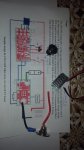
Become a Patron!

How-To & Why-To of PWM box mods

rolf 2

Bronze Contributor
Member For 3 Years
Member For 2 Years
ECF Refugee
The parts I chose can be soldered in with either a fine tip iron or a rework station. I chose them carefully so that a good fine tip iron along with rosin & flux would be enough to assemble for people with a steady hand. I've assembled about 4 of those kits myself as part of the initial testing that way. One reason the smallest part is 0805 was to make it a little easier for manual assembly, as well as using SMD chips with leads even if they are small.
fancylights
managed to get a few parts on and checket with ohm meter but then screwed up and lost the u1 ..!! it jumped some where tried everything to find it ,to no avail . not sure if I give up , or order another set or go with the essembled one . just mad at myselv . did not see any parts like the u1 on your e bay store. or if the part is available ho to ad it to an order .any direct link other than ebay ?
 

DIY FancyLights

Member For 4 Years
Yes, those things are tiny. We do have the parts listed by themselves, including the IC's in qty 1.

U1 MIC1557YM5 http://cgi.ebay.com/ws/eBayISAPI.dll?ViewItem&item=252120811164

You can also message me directly and we can arrange PP payment for any orders (which allows for a discount since no eBay fees)

Reminder that we do combined shipping, so if you decide to get more then one item via eBay, place them all in your cart and make a single payment. That will allow eBay to automatically apply shipping discounts.
 

DIY FancyLights

Member For 4 Years
fancylights
managed to get a few parts on and checket with ohm meter but then screwed up and lost the u1 ..!! it jumped some where tried everything to find it ,to no avail . not sure if I give up , or order another set or go with the essembled one . just mad at myselv . did not see any parts like the u1 on your e bay store. or if the part is available ho to ad it to an order .any direct link other than ebay ?
Tracking says a good chance you'll get the replacement today or tomorrow, good luck!
 

rolf 2

Bronze Contributor
Member For 3 Years
Member For 2 Years
ECF Refugee
Tracking says a good chance you'll get the replacement today or tomorrow, good luck!
[fancylights !
sure did get them in today . and the upgrade from 1 to 2 was not overlooked ...thanks ! now got some braid coming to clean some solder of and re flux to put more parts on . not in a hurry on that ..sure glad I got your populated board also .,which will go into my diy build next couple of days .
thanks for the super customer service !!
 
Does anyone have a wire diagram for the new NL PWM for 2 18650's. I don't want to mess it up or i would just figure it out.
 
diyfancylights, I'm build a very high powered 3s lipo mod and I ordered some of your chips. When stacking two of them together, do i have to do anything different than on the single install?
 

DIY FancyLights

Member For 4 Years
When using two stacked microFET boards with one microPWM in a 3S build make sure you do replace the 15K resistors on the microFET boards with the supplied 570K resistors. When doing the stacking I recommend a slight gap between the two boards and then making sure the high current wires between the boards are filled with solder to make a good solid block to help them there.

Having the 470K resistors on both boards is option, you really only need it on one board as long as no wires break between the boards. Those resistors when used with the microPWM are there only as a safety measure for powerdown and are not active components while pulsing.
 
Another question for fancy lights,
What would I take to set up your microfet and pwm to run 1000+ watts with a 3s lipo?
 
I realize that. My battery is good for 420 amps continuous. Just building it for stupid shit mainly, got some 40mm atomizers to throw on it and run at retarded high power.
 

DIY FancyLights

Member For 4 Years
I won't recommend or encourage you to run a rig like that. I'll let others yell at you for going too far. I just had to start with an initial realistic check. Since your asking about 1000+W from a single rig it was obvious this wasn't for a multiple vape station rig (which normally would be one PWM rig per vape.

You're talking about 3-4 microFET's wire in parallel with 3-4 14awg wire to/from them to handle the 80A reliably (I stretch it to 4 depending on how paranoid you want to be). I also recommend you run the micro PWM at a lower frequency (say 200Hz or lower?) since it may be a little slow in switching them off/on due to the capacitance. The lower frequency would help offset any excessive heating with much less heating during the full on.off cycle. This is untested and becomes more important for 4 in parallel, this is due to the capacitance on the Gate in each MOSFET. During initial testing check the MOSFET's for heating!! This is important since an problem will show up there!

If there are any issuesm I do know of a way to boost the current capabilities of the microPWM in a 3S build to handle the MOSFET's even easier by placing a different chip after the microPWM that has a higher voltage minimum but can drive much higher capacitance easier. The weak link once you have enough MOSFET's for the current is that the driver chip was selected more for 1S/2S/2P but gains performance in 3S & 4S builds. I just haven't tested their performance with that much capacitance.

I've actually considered building that for 2S-4S stuff, or 1S-4S when a voltage booster is used.
 
Okay. With running 4 chips in parallel, the wires coming off of the pwm must be run to all for chips too, correct? Do you think multiple IRLB3034 mofsets attached to individual heat sinks would be better for what I'm trying to do?
 

DIY FancyLights

Member For 4 Years
Yes, you would need to run a wire from the microPWM to each of the Gate's. At almost all voltages, the parts used in the microFET's are lower RDSon then the IRLB3034PBF. at 10+V they actually drop below 1mOhm (compared 1.4mOhm to 1.7mOhm vs 0.75mOhm to 0.99 mOhm)), so they are better then using IRLB3034's in extreme cases. The PSMN0r(-25YLC I used also have similar or lower capacitance then the IRLB3034PBF.
 

DIY FancyLights

Member For 4 Years
Just realized I may have been getting too technical on the MOSFET issue. To simplify it, at your currents you are better off with the microFET's then the IRLB3034PBF. But I know there is personal preferences which is why I carry both in my store as well.
 

DIY FancyLights

Member For 4 Years
Based on the rating sounds like a LIPO pack for RC models. Even some of those small ones are rated for 420A surge. but 420A continuous would neae some really heavy wire.
 
It's a gens ace 7000 mah 60c continuous 3s lipo, even running at just over 1,000 watts it won't even be at 25% of it's rated continuous discharge capabilities. I guess I'll run 4 of the microfets in parallel, I've got plenty of room for the retarded amount of wiring it will need so why not. I'll have to grab my temp Gun on initial testing to check temps on the mosfets. If making it pwm is a problem I could always go ahead and make it a true unregulated mod, but I'd personally rather keep it pwm.

The days of ohming out my builds to get exactly the right amount of power are gone, too much of a hassle with battery drain and what not. I'll have to keep the resistance at or above .16 to stay within 80 amps on a full battery, which is plenty easy to do on any 30 mm rda or tank.

I just preordered a 40mm mod father that I watched a beta tester hit at 700+ watts, so I'll have plenty of options to choose from for what I can run on it. I'm not looking to run 1,000 watts every day or anything, I just want to be able to if I want, as well as I will have less worries about building too low and blowing the mosfet.

I'm also putting together a smaller billet box that will be setup for daily carry and won't be nearly as ridiculous. I have a 3s battery for the but I'll probably pick up a 2s as well so I can play around with different ohm limits.

Here's the box with a 40mm dump tank on the top for size reference.
 

Attachments

  • IMG_5011.JPG
    IMG_5011.JPG
    142.3 KB · Views: 30
Well, it's together. I have to pick up some electronics grade silicone to finish it, but it worked great on bench testing. Didn't try anything stupid on it yet, but at .28 ohms it was running fine, mosfets weren't getting warm. My 40mm dump tank works great for once, was running it at 8.4 volts and I could actually hit it, no 3+ second warm up time like it had on the rx200 at 250 watts. I'm going to silicone all the boards and joints to prevent any shorting of the components, however I will leave the mosfets exposed to prevent them from overheating.

Thanks for the help and boards fancylights, wouldn't have been able to get this thing built without your help.

If anyone is curious about how well it all turned out, follow me on instagram @gatordime. I'll be posting pictures/videos of it when I have it completely finished in the next couple days hopefully.
 

DIY FancyLights

Member For 4 Years
0.28 ohms is barely a test for that setup. Mostly tests that everything is wired and works considering the specs the electronics were built around.
 
Last edited:

Cloudy Peak Vapes

Gold Contributor
Member For 4 Years
Member For 3 Years
Unlisted Vendor
I may have missed, but @gatordime what box is that? Is that a Hammond or custom CNC box? I see the lean so I'm guessing Hammond. I thought 1590B's were big... Damn. I'm pretty excited for my first PWM box. It shipped yesterday, smart PWM, dual 18650. It's in a B box to sit 30mm attys flush.

I'd love to see pics of the finished box. I just bought a soldering iron and am planning on making an unregulated mosfet box once I learn to solder well.

How do you like lipos for PWM? I know how they are in DNA's, different drain characteristics etc... I tend to prefer my 18650's but I have a 3s 1200 mah, so it's a small guy. I could see them being really good for PWM, but bad for unregulated due to their drain characteristics. Always learning.
 
Honestly, this is my first time messing with lipos and pwm. It's not quite a Hammond box, but it is diecast. Here's the link
https://www.mammothelectronics.com/products/4s1032l-looper-enclosure?variant=31841433415

I won't really be able to speak about the drain characteristics of the lipos based on this box as The battery is much larger than any other box mod. I'll let you know what I think when I build my daily carry box with a 2200 mah 3s. I'm trying to get away from 18650s, I have to buy 12+ batteries a year and it's annoying lol
 

Cloudy Peak Vapes

Gold Contributor
Member For 4 Years
Member For 3 Years
Unlisted Vendor
Honestly, this is my first time messing with lipos and pwm. It's not quite a Hammond box, but it is diecast. Here's the link
https://www.mammothelectronics.com/products/4s1032l-looper-enclosure?variant=31841433415

I won't really be able to speak about the drain characteristics of the lipos based on this box as The battery is much larger than any other box mod. I'll let you know what I think when I build my daily carry box with a 2200 mah 3s. I'm trying to get away from 18650s, I have to buy 12+ batteries a year and it's annoying lol
Cool man. I'm definitely interested to see the progress and hear your thoughts. I'm hoping to have my PWM box in my mailbox today. It's in town but scheduled for Monday, hopefully they don't sit on it. A daily carry with 2200 mah 3s I'm very interested in the battery life when you get around to it. I notice with my DNA's that my lipos sag less, but they drop to 3.7V rather quickly. However they hold that voltage until around 10% remaining charge. That, plus less sag, and PWM sounds like a great combo. Definitely a box that could push the limits. Be safe and enjoy.
 
hi everyone
can someone please help me with the connection parts?
i have to install switch,pot,push button and the voltmeter...
i'm a beginner...
thanks in advance

ps:i'm not american so it's difficult for me reading the instructions and all your comments...
 

Attachments

  • 20170225_145503.jpg
    20170225_145503.jpg
    465.3 KB · Views: 53

DIY FancyLights

Member For 4 Years
hi everyone
can someone please help me with the connection parts?
i have to install switch,pot,push button and the voltmeter...
i'm a beginner...
thanks in advance

ps:i'm not american so it's difficult for me reading the instructions and all your comments...

The wiring drawing I created for that which you have in the PDF included is:

microPWM-5014-usage_v4.png
The the switch are either on Fir or the on/off. I designed it so that the SW on the left is the Fire & on the right is on/off, but people have used it the othe3r way around. The optional Meter shown assumes a 2Wire that wokd with the PWM mode, other meters need other type of wiring. The Diode on the far left is an optional LED to show that it's firing that works if the proper R2 is installed in the microFET board thats on the Right. The pot to adjust the PWM is shown on the Left side of the microPWM board with the three wires attached.

For others that want to help in translation for him the full PDF I created is at http://www.diyfancylights.com/files/microPWM-5014-instructions.pdf
 
Last edited:
thanks for your continous help diyfancy but maybe i need some real image to understand how to put the wires properly
what do you mean for DW? do you mean SW?
i have only understood where to put the pot ahahah
 
aok ahahah
please reply me with another drowing ahah
 

Attachments

  • 20170225_155612.jpg
    20170225_155612.jpg
    709.4 KB · Views: 80
  • 20170225_155612.jpg
    20170225_155612.jpg
    709.4 KB · Views: 69

VU Sponsors

Top