Become a Patron!

Basic MOSFET wiring

Vape_geek

Member For 4 Years
Member For 3 Years
Member For 2 Years
Member For 1 Year
Member For 5 Years
Can someone help me out with basic wiring of a mosfet for a box mod.

I am trying to use a mosfet in unregulated mode just to offset the AMP current form the button.

I am building a dual 18650 box mod, and would like to use the mosfet as most momentary switches are only rated to 3 AMPS
 

Saddletramp1200

Diamond Contributor
Member For 4 Years
I have been told a 3 amp switch is fine to use. I DON"T know, so if you smoke the board don't come after Me. It's momentary so In theory it should be ok.
 

Vape_geek

Member For 4 Years
Member For 3 Years
Member For 2 Years
Member For 1 Year
Member For 5 Years
Issue is with the way a switch works that with every time you pass current that is over the maximum rating it damages the switch.

It can cause the switch to stop working which is fine, but it may cause the switch to arc and fuse the 2 contact points causing the mod to fire continuously which is very bad.
 

Saddletramp1200

Diamond Contributor
Member For 4 Years
Issue is with the way a switch works that with every time you pass current that is over the maximum rating it damages the switch.

It can cause the switch to stop working which is fine, but it may cause the switch to arc and fuse the 2 contact points causing the mod to fire continuously which is very bad.
I bought the same switch a DNA 30 has from Digikey. All I can do is try it.
 

Saddletramp1200

Diamond Contributor
Member For 4 Years
I searched for months trying to find info on building box mods. Vape forums would get pissed off because I said Damn or crap or something like that. They would ban Me. Fuck Em' I found home! No kids should Vape anyway. And if people are too high & mighty to put up with a few chosen words, they don't belong on an Adult forum. Vapor Joes has helped me make the right choices for months. If they don't like it, Fuck Em'.
 

Saddletramp1200

Diamond Contributor
Member For 4 Years
I hear you; but don't you think there is home language and public language? Doesn't bother me just saying.....;)

Do let us know how you make out with that switch please.
I hear you also. 98% of my posts contain no (foul) language. But this ain't the 700 club. If members encounter salty language, they have the option of not reading the post. I make no excuse for what I am, or who I am. I am just proud someone has the guts to provide a forum that gives Adults that choice. Had to edit this post because my internet took a dive again.
 

Cessnapix

Silver Contributor
Member For 4 Years
Member For 3 Years
Not a problem with me..........I do know some get offended. I have been told I have a colorful use of the english language before.
Sorry to interupt the thread. It wasnt that important.
 

Saddletramp1200

Diamond Contributor
Member For 4 Years
Not a problem with me..........I do know some get offended. I have been told I have a colorful use of the english language before.
Sorry to interupt the thread. It wasnt that important.
Glad to have you here. Were making fun of fat Boy on another thread. If he pisses China off, he is screwed.
 

Saddletramp1200

Diamond Contributor
Member For 4 Years
Brother Man, did you read the forum rules? If not please do. We play hard here, It's "grown up world". Thank You, drive through please. By the way, Cessna 310 & Beech T 44a are my favorite birds.
 

Cessnapix

Silver Contributor
Member For 4 Years
Member For 3 Years
lol...I use to have a cessna 150. a tad smaller.. I thought i read the rules,,,wasnt much as I remember. Will go back and look later!
 

Vape_geek

Member For 4 Years
Member For 3 Years
Member For 2 Years
Member For 1 Year
Member For 5 Years
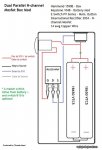
Anyone who is good with electronics, can you draw up a basic wiring diagram for an unregulated mod using a N channel Mosfet to offset the amperage form the switch.

I want to use the mosfet just as a switch without regulating the power current form the battery. I might be totally out of my depth but I believe that should be pretty simple to achieve.
 

Vape_geek

Member For 4 Years
Member For 3 Years
Member For 2 Years
Member For 1 Year
Member For 5 Years
Thanks, thats exactly what i was looking for.
 
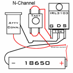
Here it is. This comes from breaktru.com, it is not mine.

I use a P channel set up in my mods. Not because it is better. It is just what I have.
I have my mosfet wired exactly like this diagram, but with a simple momentary 3a button. With or without the button installed, as soon as you install the battery - it starts firing. I'm very confused. Tried 2 different mosfets and same result. I'm using the 3034n from digikey just like a ton of other people use. The other difference from the diagram is that I'm using dual 18650's instead of a single. Any ideas why it might be auto firing? I did get it to work for about 5 pulses and then it went back to auto firing.
 

Hermit

Silver Contributor
Member For 4 Years
Member For 3 Years
Member For 2 Years
Member For 1 Year
Member For 5 Years
Have you got the resistor fitted right? That's what keeps the MOSFET 'off' when the switch isn't pressed.
 

Hermit

Silver Contributor
Member For 4 Years
Member For 3 Years
Member For 2 Years
Member For 1 Year
Member For 5 Years
Yup. Also wondered if the connections were all good, on the resistor. Only other thought would be a dodgy switch. but that's unlikely.
 
Yeah, it's driving me nuts. Changed out the mosfet to a second one and the same result. Even fired without the button in place so that's telling me the mosfet is closed. I'm using a 15k .25 watt resistor. That's what was suggested for the build. I'm scratching my head furiously while I contemplate shooting myself in the face. lol
 

Hermit

Silver Contributor
Member For 4 Years
Member For 3 Years
Member For 2 Years
Member For 1 Year
Member For 5 Years
Without the switch in there, you could try shorting the gate to source/ground. If that stops it firing, then a lower value resistor, say 2.2k. might make it work.

(I'm not certain it's something to do with the resistor that's causing the problem... but the symptom fits).
 

Cessnapix

Silver Contributor
Member For 4 Years
Member For 3 Years
Here it is. This comes from breaktru.com, it is not mine.

I use a P channel set up in my mods. Not because it is better. It is just what I have.


I think it is firing all the time because you have both legs of the switch wired in the diagram. Doesn't that by pass the switch and basiclly hard wire the switch in the on position? Shouldnt you just be using one side of the switch not running a lead across them or am I reading that wrong?

I am talking about the red lead jumping across both legs on the top and bottom. it should be wired to one side or the other but not both ??????
 

Warhawk-AVG

Silver Contributor
Member For 5 Years
MOSFET

Gate, Source, Drain

Think of it as a solid state "relay"

If you pull the gate to either ground or put voltage on it, it "closes" the switch

1107px-Mosfet_n-ch_circuit.svg.png


The LED on the schematic...that is the "coil" on your rig

I build flashlight drivers for fun...we use pretty good MOSFET's on em...

Just remember, it's an electronic on/off switch..very little power is lost in the MOSFET...when you hit the tiny momentary button (can use low current switch) it unleashes EVERYTHING capable behind it upto it's rated capacity

This is a VERY capable MOSFET (small Rds on)
http://www.digikey.com/product-detail/en/AOD510/785-1481-1-ND/3603497


Hope that helps (anyone that doesn't understand electronics...not the OP)

On your schematic OP, take the bottom side of the tact switch, tie in a couple hundred ohm resistor to battery - (to limit current thru the switch) and viola
tact_touch_n-ch-jpg_thumb-png.1330


Actually I see the 15K between the G and S pins...looks pretty good actually

Googled this up...different use..but wiring the principle is the same
Simple-MOSFET-Setup-2009-06-22.jpg
 
Last edited:

Warhawk-AVG

Silver Contributor
Member For 5 Years
Nice!

Back of the case can be used as the negative lead as well (larger surface to solder to)

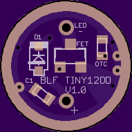
Question? Would a small 1/2" PCB where you can surface mount the FET to with VIA holes in it be useful for those that want to DIY?

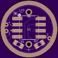
Something like this (example of a very small multimode flashlight driver I helped work on)
The VERY small MOSFET can push well above 6A to a flashlight emitter)
https://oshpark.com/shared_projects/JjjreYAS
i.png


This way it has the holes in the board, all you do is mount the MOSFET to the board, and solder the wired into the holes and done...or is that just too much work
i.png

(P.S. The small ATtiny MCU can be programmed to offer PWM to the MOSFET thus you can adjust the power to the coil (similar to a kick or Vamo type vape)

Which coincidentally looks and operates ALOT like a kick
 
Last edited:

Cessnapix

Silver Contributor
Member For 4 Years
Member For 3 Years
Nice!

Back of the case can be used as the negative lead as well (larger surface to solder to)

Question? Would a small 1/2" PCB where you can surface mount the FET to with VIA holes in it be useful for those that want to DIY?

Something like this (example of a very small multimode flashlight driver I helped work on)
The VERY small MOSFET can push well above 6A to a flashlight emitter)
https://oshpark.com/shared_projects/JjjreYAS
i.png


This way it has the holes in the board, all you do is mount the MOSFET to the board, and solder the wired into the holes and done...or is that just too much work
i.png

(P.S. The small ATtiny MCU can be programmed to offer PWM to the MOSFET thus you can adjust the power to the coil (similar to a kick or Vamo type vape)

Which coincidentally looks and operates ALOT like a kick

Very interesting; I find that intruiging and wish I new more about electronics. I have been trying to figure a way to use a vamo board in a bottom feed device and there is so little room. I like the idea of using two batteries in the buck state. This might fit that role nice. I am using the Crown at the moment vs the kick because it has the modes settable buy the fire button and audible feedback rather than just a turning a pot on the kick.

Now that I understand the mofset is just a solid state relay. This makes more sense to me.

And this device would be nice. i will have to look at more when I have time. Thanks
Very interesting!
 

robtest

Bronze Contributor
Member For 4 Years
Member For 3 Years
Member For 2 Years
Member For 1 Year
Member For 5 Years
Would a negative chassis connection be good ??? Since you are using the N-Channel Mosfet Dump Channel to feed the negative connection to the 510, and the positive is always connected to the 510 pin, I would think that a negative chassis would give you an always closed circuit... :confused:
 
First post. I actually found this site and this thread while search for wiring diagrams for a mosfet box mod. The schematics you guys have shared have been a enormous help, thank you for sharing.

I am new to wiring electronics like this and I don't know a whole lot of the jargon associated with it (I do have some wiring and soldering skills from working on cars and motorcycles though). I have a question though, I went to my local Radio Shack looking for some parts and I couldn't find any 15k .25w resistors. They had 10k .25w and 22k .25w. Would either of those work or is 15k the sweet spot? They also didn't have any 14 gauge wire, only 12 or 18. Is 12 too big or does it matter?

Thanks in advance for any answers or comments and thanks again for sharing what you guys have already shared.
 

Hermit

Silver Contributor
Member For 4 Years
Member For 3 Years
Member For 2 Years
Member For 1 Year
Member For 5 Years
Welcome to VU :D

Too big a wire is fine as long as you can manage to solder it :)

The 15k is probably not too critical, 10k should work just as well.

(disclaimer: I haven't built this circuit, but I do have electronics experience)
 

Warhawk-AVG

Silver Contributor
Member For 5 Years
First post. I actually found this site and this thread while search for wiring diagrams for a mosfet box mod. The schematics you guys have shared have been a enormous help, thank you for sharing.

I am new to wiring electronics like this and I don't know a whole lot of the jargon associated with it (I do have some wiring and soldering skills from working on cars and motorcycles though). I have a question though, I went to my local Radio Shack looking for some parts and I couldn't find any 15k .25w resistors. They had 10k .25w and 22k .25w. Would either of those work or is 15k the sweet spot? They also didn't have any 14 gauge wire, only 12 or 18. Is 12 too big or does it matter?

Thanks in advance for any answers or comments and thanks again for sharing what you guys have already shared.

You could probably use the 22k no problem...the resistor is there just to prevent too much current from flowing thru a low current momentary push button (if you have a 3A push button the 10K will work just fine), think of it as a current "restrictor" for the switch, the ground will still flow thru to the gate and activate the MOSFET

Thicker the gauge wire the less internal resistance it has (can push more current w/o heating up)...only problem is, thicker wire means it takes up more space but if you have space for it go for it

I use 22ga silicon covered wire in my flashlights that I push 5A+ thru to the emitter...got 1 meter each of black and red from FT for $.99, stuff is VERY flexible and can really handle the current, plus the insulation doesn't melt if you get it a little hot from soldering
 
Last edited:
Thanks for the responses! The switch I will be using is a 2A switch. I've got a few 15k resistors on the way, so I will use one of those. I think I might get some of the 18ga wire that Radio Shack had or try somewhere else to find 14ga. I can solder the 12ga with out any issues but I don't think it's flexible enough to squeeze everything into my box.

Thanks again for the responses!

Update: I got some 14ga wire and I've got some 15k resistors on the way from digikey. I decided to pump the brakes and do things the way I wanted them done instead of trying to take shortcuts.
 
Last edited:

robtest

Bronze Contributor
Member For 4 Years
Member For 3 Years
Member For 2 Years
Member For 1 Year
Member For 5 Years
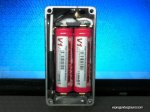
Read all about it, ordered some parts, joined some groups on FB, saved lots of pictures, ...
Dusted off the soldering iron, broke out the 2x reading glasses, ...
And it can be done... :p

aa_mosfet_1_zps14a5abf2.jpg


aa_mosfet_3_zps96315732.jpg

aa_mosfet_4_zps50a68156.jpg


aa_mosfet_5_zpscfb095c2.jpg
 

Warhawk-AVG

Silver Contributor
Member For 5 Years
Nice....aluminum boxes...where are you getting them? Pretty big, what is it measurements?

Either way..wicked cool man! Definitely need to look into getting a charge module in that somehow...this way you don't have to keep opening it to change out batteries (as often)

I wonder if aluminum interferes with Qi inductive charging?
 
MOSFET

Gate, Source, Drain

Think of it as a solid state "relay"

If you pull the gate to either ground or put voltage on it, it "closes" the switch

1107px-Mosfet_n-ch_circuit.svg.png


The LED on the schematic...that is the "coil" on your rig

I build flashlight drivers for fun...we use pretty good MOSFET's on em...

Just remember, it's an electronic on/off switch..very little power is lost in the MOSFET...when you hit the tiny momentary button (can use low current switch) it unleashes EVERYTHING capable behind it upto it's rated capacity

This is a VERY capable MOSFET (small Rds on)
http://www.digikey.com/product-detail/en/AOD510/785-1481-1-ND/3603497


Hope that helps (anyone that doesn't understand electronics...not the OP)

On your schematic OP, take the bottom side of the tact switch, tie in a couple hundred ohm resistor to battery - (to limit current thru the switch) and viola
tact_touch_n-ch-jpg_thumb-png.1330


Actually I see the 15K between the G and S pins...looks pretty good actually

Googled this up...different use..but wiring the principle is the same
Simple-MOSFET-Setup-2009-06-22.jpg
Is that particular mosfet you linked applicable to a mechanical mod? I hope so, just ordered 5 of them lol
 

Hermit

Silver Contributor
Member For 4 Years
Member For 3 Years
Member For 2 Years
Member For 1 Year
Member For 5 Years

robtest

Bronze Contributor
Member For 4 Years
Member For 3 Years
Member For 2 Years
Member For 1 Year
Member For 5 Years
twice the price but still under $5 ... the 3034 is the mosfet of choice ...
 

Wabah58

Silver Contributor
Member For 4 Years
Tactile switch from ebay, same ones used in the Cana mods, on the 18650 box. With mosfet takes the amps off the switch, so you can use almost any switch.

http://www.ebay.com/itm/331316359800

You can use 12mm or 16 mm heavy switch too, still should use mosfet, but they are very big.

 
Last edited:

robtest

Bronze Contributor
Member For 4 Years
Member For 3 Years
Member For 2 Years
Member For 1 Year
Member For 5 Years
I used the 16mm in my box mod... Careful on going too cheap, as it will be coming on a slow boat from China ... :confused:
 

Resnik

Member For 4 Years
Member For 3 Years
Member For 2 Years
Member For 1 Year
Member For 5 Years
Ok I feel a bit like a idiot, but eh live, screw up, and learn. I had been looking through forums for a while about building a box mod. I read everything I thought I needed to know and I found all the parts I thought I needed. I ordered parts today from a shop on eBay that had just about everything I needed, but for a 510. That I picked up from Varitube.com. So I get to reading some more thinking I should do as much research as I can before I start to put this thing together. After looking through post in this thread one thing that popped up was what type of mosfet or more what exact part number you showed a few post up as the "mosfet of choice". THEN went back to what I had ordered and noticed the one I bought said P channel. So I came back here and saw the ones you listed were N channel mosfets. So I went and did more reading and understanding what the difference is. Basically it confused me and I'm not sure I can even use it. Thinking about just ordering whats normally used, but thought maybe it could be used and it's just beyond my general understanding.

The mosfet I ordered is: SUP75P03-07-E3

Evidently this type of mosfet is normally used in building a VV Raptor box mod.
 

robtest

Bronze Contributor
Member For 4 Years
Member For 3 Years
Member For 2 Years
Member For 1 Year
Member For 5 Years
so basically that is a positive channel mosfet rather than the N channel that most people use... I have read some things about those being used. The chip that you have specified looks a little lightweight... The continuous drain is 75A vs 195A on the 1034 Nchannel and only 3.75W Power Max (unless that is a typo) vs. the 375W on the 1034 ... I think if you had a better chip it would work, but this one wouldn't... But then again, I am surprised by the number of people that straight wire up one of the cheap switches off of ebay thinking it is really 60w ... And they seem to work so IDK...

http://www.digikey.com/product-detail/en/SUP75P03-07-E3/SUP75P03-07-E3-ND/2623113

http://www.digikey.com/product-detail/en/IRLB3034PBF/IRLB3034PBF-ND/2096638


This is a really good group on FB: https://www.facebook.com/groups/745177428867028/
 

VU Sponsors

Top