Become a Patron!

Bolt from fasttech

DadyGoble

Member For 4 Years
Member For 3 Years
Member For 2 Years
Member For 1 Year
Member For 5 Years
My wife just got her fasttech bolt and it was working great alllast night but now it wont fire any RDA that she has (she has no sub ohm builds) it was firing a gbc tank but now it wont even fire that ive tried a fresh battery a 510 to ego adapter. What could be wrong.
 

DadyGoble

Member For 4 Years
Member For 3 Years
Member For 2 Years
Member For 1 Year
Member For 5 Years
Never mind I figured it out the wire from the positive post to the switch was broken. Super easy to fix just a blob of solder. This video helped alot its called modding the bolt 101
 

DadyGoble

Member For 4 Years
Member For 3 Years
Member For 2 Years
Member For 1 Year
Member For 5 Years
Yea I vaped on her bright pink bolt all last night after I fixed it and it is a good performer for the mony. I am considering tearing it back apart and modding it with alot heavier guage wire and a better button for sub ohm vaping.
 

Warhawk-AVG

Silver Contributor
Member For 5 Years
At least 22ga wire, they sell some very flexible silicon wire at FT , used it in my flashlights, push upwards of 5-7 amps with no heat and minimal loss

Looking at the build of the contact plate in the push button top part, I might be able to whip up a simple PCB replacement that has a SOT-23 sized IRLM2502 MOSFET, won't need to beef up The switch and all the power will flow to the head then (some of those switches have pretty high internal resistances)

I forgot to mention that I have a madvapes extension on mine w/ a 18650 (for a total if 2) and a kick, I don't vape at high watts (my kanger protank/bottom coil tanks at 6.5 watts, and the genesis style RBA's at 8 watts)

Posted from NARFatalk!!
 
Last edited:

DadyGoble

Member For 4 Years
Member For 3 Years
Member For 2 Years
Member For 1 Year
Member For 5 Years
Tonight the switch burned out in my wifes bolt so I tor out the switch and rewired the device aswelk as ordering her a new switch. Could you by chance send me a how to on the pcb and mosfet setup. Thanks
 

Warhawk-AVG

Silver Contributor
Member For 5 Years
Yeah, I will measure the plate and design up the board, I have to also make some measurements for clearance and whatnot

Posted from NARFatalk!!
 

DadyGoble

Member For 4 Years
Member For 3 Years
Member For 2 Years
Member For 1 Year
Member For 5 Years
Ah man thanks I realy apreciate it and if there is anything I can do for you just let me know.
 

Warhawk-AVG

Silver Contributor
Member For 5 Years
OK...whipped up a quick board

The diameter of the plastic base in the top part is 20mm, the center pin is 6mm but I think one of those 5mm dia x 2mm tall brass buttons from fasttech will do nicely.

only 4 connections (switch 1 and 2, and the battery center to the center connector on the 510, and the gnd to the body of the 510) and 2 components, the AOD510 from above and a 0805 15-22K ohm SMD resistor.

3D rendering
TOP:
top_zps4acddf4f.png


Bottom:
bottom_zps1868fc95.png


The reason the FET and resistor are so far off on one side is the switch inside the bolt top only has a tiny bit of clearance on one side, but opens up on the back side allowing for more room for the FET.

This is a preliminary build...I plan on tweaking it a bit

Also the stock plastic board is 2mm thick..boards from OSHPark are 1.6mm thick...don't think it will be an issue...but wanted to put that out there

The thruholes should be big enough to fit at least 22ga wires thru them
 
Last edited:

Warhawk-AVG

Silver Contributor
Member For 5 Years
Ok, gonna move the resistor between the legs of the FET, run a via to the bottom, small trace over to the via on the drain of the FET (the large pad)

The large copper pours and extra vias in the battery connection side are for extra current flow capability...I might reduce the copper pad to 5mm, those little pillars work very well and center perfectly on a 5mm copper circle, just hit em with solder and they are down solid

I work nights and it's WAY past my bedtime...will work on this after I get up
 

Warhawk-AVG

Silver Contributor
Member For 5 Years
Thinking of making a polygon pour on the battery side under the solder mask then some VIA's under the ground pad, will use the copper as a heatsink, still have a few projects in the works, also might modify a TO-220 regulator board I have in my oshpark profile, be able to thru-hole the components on a nice neat PCB

Posted from NARFatalk!!
 

DadyGoble

Member For 4 Years
Member For 3 Years
Member For 2 Years
Member For 1 Year
Member For 5 Years
You went a little over my head with the tech jargen but if I kept up it sounds like you are wanting to make the bolt VW/VV. is that correct?
 

Warhawk-AVG

Silver Contributor
Member For 5 Years
No, make it MOSFET driven, instead of having power flow thru the switch (which can have high resistance connections that bleed power thru heat and waste the energy that should flow to the coils in the switch or body ), they say it's capable of 30A but you know how well Chinese hardware may or may not meet "specs" , with the FET, small current can control a huge current

Think box mod but In a tube

Posted from NARFatalk!!
 
Last edited:

Warhawk-AVG

Silver Contributor
Member For 5 Years
Heck with what we do with MCU's (micro control unit...aka a 20mhz computer on a chip the size of your pinky fingernail) on our flashlight drivers we could make it not fire if battery volts got too low, and only fire for 10 seconds. More or less build battery protection into the head of the bolt

Sure you get the exact same or better from pre-built rigs like the Vamo, but that whole DIY tinker thing

Posted from NARFatalk!!
 

DadyGoble

Member For 4 Years
Member For 3 Years
Member For 2 Years
Member For 1 Year
Member For 5 Years
That is super cool man
 

Warhawk-AVG

Silver Contributor
Member For 5 Years
Well got my "test" revision up with a bmp signature silk screen on there (think P-40)

Top:
c1414875-ad08-4a63-bd16-5e010d53cf38_zpsb5c6f28a.png


Bottom:
90f18824-7f04-4c6a-ab8a-a980d3c3720d_zpsb1b3d514.png
 

DadyGoble

Member For 4 Years
Member For 3 Years
Member For 2 Years
Member For 1 Year
Member For 5 Years
What would one of these cost
 

Warhawk-AVG

Silver Contributor
Member For 5 Years
Boards are $3~ from OSHPark [I don't have it shared yet (I haven't tested the prototype yet)], the 20K 0805 resistor is like $.50-$1.00 for 10, and the AOD510 MOSFET is .81 a piece

Board: 2 layer board of 0.79x0.79 inches (20.12x20.12 mm). Your design will cost $3.10 per set of three.

So what $3.10 + $1.00~ + $2.40~ (shipping USPS first class is like $3~) so about $10 for 3, so about $3 a piece

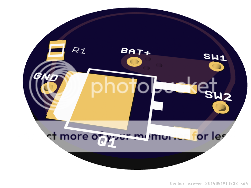
Then you just build them (SMD can be built with solder paste, and either a hot air gun or even dropping the board on a stainless steel frying pan and heating on the stovetop, or even with a soldering iron), solder the leads from the switch to SW1 and SW2, the + wire from the center via to the center pin on the 510 connector, then GND to the outside of the 510 connector

Push the button, the button pulls very small current between the + trace thru R1 activating U1's gate and full current flows from source to drain thru the coil in the vaping head screwed into the 510 connector, and voila...your mechanical possible crappy push button bolt now becomes a solid state "Lightening Bolt" :D

like I said though, untested...so I don't even know if they will fit, the schematic of the MOSFET was simple enough, but making sure it fits in the bolt around that big ole switch (which you could use a very small momentary switch now)
 
Last edited:

Warhawk-AVG

Silver Contributor
Member For 5 Years
Did some googling, found a 16mm push button that is in the bolt from some vaping modders sights
http://www.modmaker.co.uk/16mm-Nickel-Plated-Brass-Momentary-Push-Button-Switch
Apparently these things ain't rated for that high a current...2-3A max!

With the above board, the MOSFET can handle upwards of 20A so no worries there...and only a fraction of an amp flows thru the resistor to operate the gate of the FET at 4.2vdc

I need to order me some boards and components and see how it all works together (I use my bolt w/ a kick right now and an extra battery extension w/ an 18650, not sure if the FET would work w/ a kick)

Guess I need to go ahead and disassemble mine completely and check it out

I could also build a square board that holds the TO-220 type packages, and do the same thing for "box mods"
I got a project I tweaked at OSHPark right now that all I would have to do is tweak it up a tiny bit more and now those guys that do mod box mods will have a nice pretty PCB to solder to instead of just hodge podging em all together and hope the wires don't short unless they use heat shrink tubing
 
Last edited:

Warhawk-AVG

Silver Contributor
Member For 5 Years
Got it apart, the 510 connector is only pressed into the head, the push button doesn't have any marking on it at all, gonna have to re-hot glue the switch back in (had to dig the glue out with my small keychain pocket knife)
I must say the 510 connector was leaking and the inside of the bolt is filthy, going to have to soak it in rubbing alcohol or something to clean it up

Going to go ahead and order the boards and the components and try to build one

I really like the look of this 510 connector w/ the locking nut on the back, I think the fasttech bolt is 21mm diameter so the 22mm diameter one won't work unless you make a makeshift mandrel and use hobby files to turn it down a mm or so, the 14 mm will fit good enough but have a lip
http://www.varitube.com/510-Connector--Self-adjusting-Center-Pin--14mm-22mm-285mm_p_141.html

I know fat daddy vapes sells something like this as well, plus there are these
1672746.jpg

Drill out the top, tap it, screw these in then put the brass washer on the bottom side locking it in (also where you would solder the ground wire to)
In fact this guy has a TON of nice stuff!
http://www.fatdaddyvapes.com/shop.html
 

Vapecloud

Member For 4 Years
Member For 3 Years
Member For 2 Years
Member For 1 Year
Member For 5 Years
My wife just got her fasttech bolt and it was working great alllast night but now it wont fire any RDA that she has (she has no sub ohm builds) it was firing a gbc tank but now it wont even fire that ive tried a fresh battery a 510 to ego adapter. What could be wrong.

I had a friend who told me the bolt can easily be cross-threaded and mess it up. I just wanted to bring that to your attention. I tried his and it hit pretty good.
 

VU Sponsors

Top