Is this thread still alive? I see the last post was October 12th 2014. I read the whole thread on this subject, and just needed a little clarification.
I was thinking of using a much bigger Hammond Enclosure Box, and using a LiPo 14.8v 90C 5000mAh Batter as my power source..
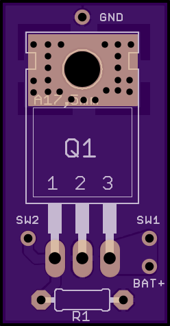
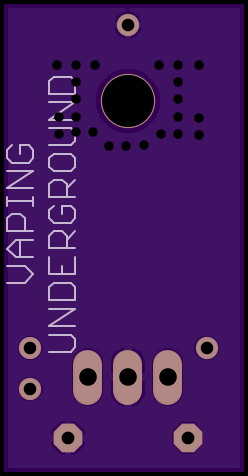
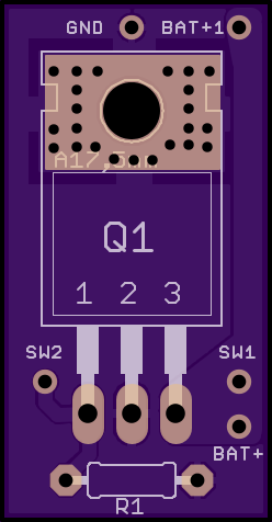
So.. I went and just basically re drew what I thought was right..
View attachment 7524 View attachment 7524
Is that good, or is it wrong? I could also use 26650 MNKE IMR Batteries, which is what I have already.. I'll probably need a 26650 Cradle to hold the batteries.. I just basically want to create a Box Mod that gives me the freedom to vape at any wattage I want, and not have to worry about limits anymore. The above mod will allow me to vape up to 375 Watts, which from what I've heard other places usually ignites the eLiquid. lol.
But anyways, yeah, that's what I want to make. I'll call my Box Mod, (THE HULK). Because I also know of on "MOUSER" that there's N-Channel MOSFETS higher than the one listed above. So.. I'm actually a little new to MOSFETS. I watched the video already. No need to post it again.
I actually would like the freedom to be able to vape at 500 Watts, or past 500 Watts. Using the above setup. The problem with this is that I do not have a solder iron, I do not know what type of solder to use.. I could probably just use pure silver solder from Rio Grande online.. I hear Silver is the BEST conductor. But anyways.. What type of solder do I need for this little project, and what type of solder iron do I need? I'll probably also be using heat shrink tubing for the 4mm bullet connectors for the battery. I'll have to take the battery out and charge it with a battery charger from Hobby King.
Awesome thread & Forum BTW. Absolutely love all the information on here. Been looking for some real help, and just been a little nervous starting this project. But I would ABSOLUTELY LOVE to make my own box mod. You guys seem really smart and really easy going and seem to know your stuff. I currently own 1 Mechanical Mod, it's the Pure Copper Hades.
I mainly shop at McMaster-Carr, Lowes, etc. etc. for most of my stuff when it comes to building things.
")