Become a Patron!
You are using an out of date browser. It may not display this or other websites correctly.
You should upgrade or use an alternative browser.
You should upgrade or use an alternative browser.
Basic MOSFET wiring
- Thread starter Vape_geek
- Start date
VapeTechnologies
VapeTechnologies LLC Advanced Custom Boxes
VU Donator
Member For 4 Years
Member For 3 Years
Member For 2 Years
Unlisted Vendor
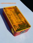
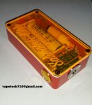
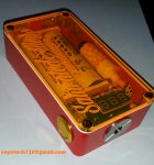
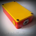
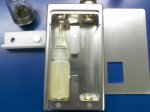
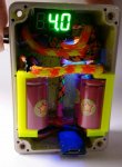
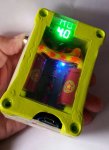
So I've got this childish project going on. I call it childish because it's going to look like a god damn night club when it's done. I got a blue laser diode about the size of a standard drip tip, that's going inside this orange box. I have a kid engraving me a clear/transparent orange lid with my logo, (taking him longer than he said it would though) you you'll be able to see the insides. Now the laser will be mounted inside the box ( uses under 200mAh) and on each side of the box on the insides I'll be running 2 small strips of reflective tape, so when the laser hits the tape, the beam bounces back and fourth a billion times, illuminating the hell out of the insides of the box in "laser mode". ....................Yea, I know...
Now I tested the theory and all is well, as long as I get the laser mounted perfectly to bounce off the reflective tape. This ain't my style of vaping, but with some of these "hipsters" (as @Wabah58 like to call them) that vape as a "sport" and treat it like the fashion industry, it's basically going to be a dream box for the scene kids/hipsters/ravers/party kids. It will be a good piece for the portfolio too. It's also going to come with this yellow lid, which will be able to stack on top of the clear lid with magnets if one chooses to rock it in such a way.
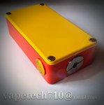
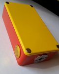
Moving right along, been playing around with a lot of engraving/etching the past few weeks. It took a lot of trial and error to get a design I can actually show you guys a picture of. I've got it down now, so the next etched box will have a lot of detail and much more "etched" surface area. THIS is more of my style...


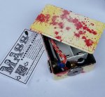
And last but not least, just for some visual fun, here's one I sold to a friend for a VERY reasonable price. Selling boxes, well some people like to knock it, but if you can make a few bucks doing something you like to do, I call that a form of success. As long as your not taking advantage of newbs or building unsafe mods, by all means, support an American market. To the people who like to talk trash about guys selling boxes, let me know how your clones from china work out for you in a few years. Nobody's ever ran their mouth to me personally, but I see a lot of it on social media.



Now I tested the theory and all is well, as long as I get the laser mounted perfectly to bounce off the reflective tape. This ain't my style of vaping, but with some of these "hipsters" (as @Wabah58 like to call them) that vape as a "sport" and treat it like the fashion industry, it's basically going to be a dream box for the scene kids/hipsters/ravers/party kids. It will be a good piece for the portfolio too. It's also going to come with this yellow lid, which will be able to stack on top of the clear lid with magnets if one chooses to rock it in such a way.


Moving right along, been playing around with a lot of engraving/etching the past few weeks. It took a lot of trial and error to get a design I can actually show you guys a picture of. I've got it down now, so the next etched box will have a lot of detail and much more "etched" surface area. THIS is more of my style...


And last but not least, just for some visual fun, here's one I sold to a friend for a VERY reasonable price. Selling boxes, well some people like to knock it, but if you can make a few bucks doing something you like to do, I call that a form of success. As long as your not taking advantage of newbs or building unsafe mods, by all means, support an American market. To the people who like to talk trash about guys selling boxes, let me know how your clones from china work out for you in a few years. Nobody's ever ran their mouth to me personally, but I see a lot of it on social media.


I like that etched box, that is my style too.
The disco laser box will be hot item, younger vapers would pay top dolla for that around here.
Love the box porn. i really been having trouble getting time to build at work If things dont change I might have to build at home.
EDIT: NO WAY!
The disco laser box will be hot item, younger vapers would pay top dolla for that around here.
Love the box porn. i really been having trouble getting time to build at work
EDIT: NO WAY!
B box got a g on the bench. Just no time to mess with right now. I also have an Okr I'm putting in an A. Haha. That's taking some patienceView attachment 19222View attachment 19223
Sent from my iPhone using Tapatalk
How you liking the PWM? Is the hipe real?
VapeTechnologies
VapeTechnologies LLC Advanced Custom Boxes
VU Donator
Member For 4 Years
Member For 3 Years
Member For 2 Years
Unlisted Vendor
@Dutzy is that granny smith green powder coat? By tony? lol I've got the same one..
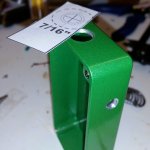
Thanks @Wabah58 , can't wait to see how the PWM comes out. I checked out some myself but I'm saving my pennies for a batch of SX chips, the 2-day battery life sold me and the DNA's are going too mainstream. The SX350's look real simple to wire up. Next project for me is going to be the SX350 w/ on board charging. I got one of the white boards we were talking about the other day.

Thanks @Wabah58 , can't wait to see how the PWM comes out. I checked out some myself but I'm saving my pennies for a batch of SX chips, the 2-day battery life sold me and the DNA's are going too mainstream. The SX350's look real simple to wire up. Next project for me is going to be the SX350 w/ on board charging. I got one of the white boards we were talking about the other day.
Haha Yes it is..@Dutzy is that granny smith green powder coat? By tony? lol I've got the same one..
View attachment 20042
Thanks @Wabah58 , can't wait to see how the PWM comes out. I checked out some myself but I'm saving my pennies for a batch of SX chips, the 2-day battery life sold me and the DNA's are going too mainstream. The SX350's look real simple to wire up. Next project for me is going to be the SX350 w/ on board charging. I got one of the white boards we were talking about the other day.
Well I joined vapingunderground just so I could say this
THANK YOU TO EACH AND EVERY PERSON WHO HAS CONTRIBUTED TO THIS THREAD.
I just ordered all the parts to make my first box. And the only question I have is I like color on my box but don't want a wrap. So what holds up good that I can do myself.
Once I start my build I will post pics often and any pointers are appreciated
Well I joined vapingunderground just so I could say this
THANK YOU TO EACH AND EVERY PERSON WHO HAS CONTRIBUTED TO THIS THREAD.
I just ordered all the parts to make my first box. And the only question I have is I like color on my box but don't want a wrap. So what holds up good that I can do myself.
Once I start my build I will post pics often and any pointers are appreciated
Cool we love pics on this thread, welcome. Im a terrible box painter but I have some decent results with the rattle can hammer tone paints. Maybe some other will chime in about the paint, it's my weakness
So first thing I'm glad of. Bought both 18650 and 26650 sleds. Didn't think the 26650 would take up all the room in a b box. Not sure my first box should be trying to put all wires in the top section. Lol
I have a question. What is the best way to cut the corner of the battery sled to make it fit around that screw post? I don't have a dermal or I think my question would be answered. I'm in the process of starting my first build. All parts on their way to me! Thanks for all your help.
So first thing I'm glad of. Bought both 18650 and 26650 sleds. Didn't think the 26650 would take up all the room in a b box. Not sure my first box should be trying to put all wires in the top section. Lol
Dual 26650's will take all the room on the sides in a B box with a 3d printed sled or a keystone. Lot of room up top.
I have a question. What is the best way to cut the corner of the battery sled to make it fit around that screw post? I don't have a dermal or I think my question would be answered. I'm in the process of starting my first build. All parts on their way to me! Thanks for all your help.
Hand file, or grinding wheel.
Thank you! I have a hand file.Hand file, or grinding wheel.
DIY FancyLights
Member For 4 Years
How about wiring the switch to apply power to the PWM, remove the PWM power switch (but leave the PWM bypass switch). That should still work for vaping and the PWM will automatically power down when not in use.
VapeTechnologies
VapeTechnologies LLC Advanced Custom Boxes
VU Donator
Member For 4 Years
Member For 3 Years
Member For 2 Years
Unlisted Vendor
The mosfet that highdesertvapes.com sales. It's not a N is it.
I didn't think to check before I ordered and now that I have it I thought to look.
I didn't think to check before I ordered and now that I have it I thought to look.
Finished up my work beater box. PWM (Pulse Width Modulation) build. I have to say PWM is pretty intense! Power is amazing.
I think I can clean up the next PWM build now that I have the 1st one under my belt and learned a few things. Have 1 more pot and board so I guess the G plus box will be next.
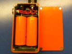
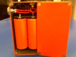
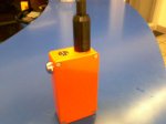
I think I can clean up the next PWM build now that I have the 1st one under my belt and learned a few things. Have 1 more pot and board so I guess the G plus box will be next.


Last edited:
Finished up my work beater box. PWM (Pulse Width Modulation) build. I have to say PWM is pretty intense! Power is amazing.
I think I can clean up the next PWM build now that I have the 1st one under my belt and learned a few things. Have 1 more pot and board so I guess the G plus box will be next.
Nice work man! I have a quick question. Where did you get your pwm board from? I am in no way ready for that type of build yet but would like to give it a whirl in the future after tons more of research! I would like to have the site bookmarked when the time is right! Thanks.
I used this board here https://oshpark.com/shared_projects/DVDAWZ6eNice work man! I have a quick question. Where did you get your pwm board from? I am in no way ready for that type of build yet but would like to give it a whirl in the future after tons more of research! I would like to have the site bookmarked when the time is right! Thanks.
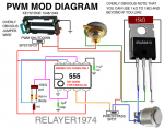
Parts for that board are DIP8 Socket (optional) 555 Timer .01uf 50V capacitor 0805 .1 uf 50V capacitor 0805 1K resistor 0805 1N914 or 1N4148 diode (x2) (soldered to pot) 10K ohm potentiometer.
This guy has some real nice stuff too. https://oshpark.com/profiles/david4500/page/1
There are a few other guys now offering complete boards populated with switches and pots already installed that are real easy to drop in. They look pretty nice but have to pay a little more. Here is one already complete that drops in the side of a g box
https://squareup.com/market/themodfatherinc
Thank you again sir for the great info! This is turning into such a fun hobby!I used this board here https://oshpark.com/shared_projects/DVDAWZ6e
Parts for that board are DIP8 Socket (optional) 555 Timer .01uf 50V capacitor 0805 .1 uf 50V capacitor 0805 1K resistor 0805 1N914 or 1N4148 diode (x2) (soldered to pot) 10K ohm potentiometer.
This guy has some real nice stuff too. https://oshpark.com/profiles/david4500/page/1
There are a few other guys now offering complete boards populated with switches and pots already installed that are real easy to drop in. They look pretty nice but have to pay a little more. Here is one already complete that drops in the side of a g box
https://squareup.com/market/themodfatherinc
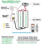
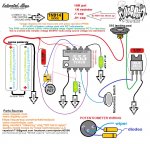
This is the first photo that shows going from switch to battery and then to 510. Most show it connecting between battery and 510. Is this right. Cause I had been thinking it would be easier to run this way and just wanted to make sure it was safeMade this a few weeks back for a FB group. It's not like there's already 100 of the same diagrams out there already, just wanted to make my own to print out and keep at a few shops I deal with.. here's to the new jacks on board. Keep the thread going guys! I'll be waiting for some pics
View attachment 20344
VapeTechnologies
VapeTechnologies LLC Advanced Custom Boxes
VU Donator
Member For 4 Years
Member For 3 Years
Member For 2 Years
Unlisted Vendor
This is the first photo that shows going from switch to battery and then to 510. Most show it connecting between battery and 510. Is this right. Cause I had been thinking it would be easier to run this way and just wanted to make sure it was safe
It's exactly how I've been wiring my boxes since day one. As far as being "safe", I believe that a unregulated box mod is only as safe as the person operating it.
Let's look at the load coming off the battery to 510. That's a source, so no matter where you splice the switch wire from, it's still carrying a load throughout the entire "red" zone. The electrons are populating any positive lead at all times. They are just sitting there, they are not active and have no place to go, but they are still there. When you complete the circuit by means of a momentary switch and give the electrons a place to go it creates the current. This is basic electronics and it's probably a good thing to have prior knowledge of when building an unregulated high amp device of any sort. I'd suggest looking up some info on electrons and how they work and how they create a current before going any further. Hope that helps. Keep us updated with the progress.
VapeTechnologies
VapeTechnologies LLC Advanced Custom Boxes
VU Donator
Member For 4 Years
Member For 3 Years
Member For 2 Years
Unlisted Vendor
VapeTechnologies
VapeTechnologies LLC Advanced Custom Boxes
VU Donator
Member For 4 Years
Member For 3 Years
Member For 2 Years
Unlisted Vendor
It's exactly how I've been wiring my boxes since day one. As far as being "safe", I believe that a unregulated box mod is only as safe as the person operating it.
Let's look at the load coming off the battery to 510. That's a source, so no matter where you splice the switch wire from, it's still carrying a load throughout the entire "red" zone. The electrons are populating any positive lead at all times. They are just sitting there, they are not active and have no place to go, but they are still there. When you complete the circuit by means of a momentary switch and give the electrons a place to go it creates the current. This is basic electronics and it's probably a good thing to have prior knowledge of when building an unregulated high amp device of any sort. I'd suggest looking up some info on electrons and how they work and how they create a current before going any further. Hope that helps. Keep us updated with the progress.
the reason I haven't started wiring it all in yet is for the reason you stated. I thought I had a beginners level of electrical knowledge. So it's basically the mosfet that stumped me. How do you run a negative wire to it and then to the button and from the button to a battery. Everything I have read just states it takes the load of the switch. But if you only have a ground going t
@VapeSignals Just go by the schematics in this thread, and go for it. It will either work or it won't. Don't over think it!
i know the schematics will work. And after going through most of the night looking at it from a different view. I'm now understand that the button is tell the mosfetthe to let the negative connect. That's all I can figure.
Mau
Member For 4 Years
Member For 4 Years
Member For 3 Years
Member For 2 Years
Member For 1 Year
New Member
Member For 5 Years
hi there, i am new on this forum.. so heres my entry for the modders
some box pictures of mine hope you like it
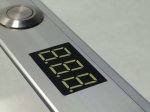
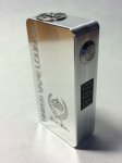
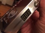
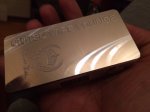
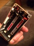
Forgot to tell. Cnc hammond 1590g. Serieel. Mosfet switch. Mitec button Positiv straight on the keystone tab. And alao the source of the mosfet on the negatif. So no thick wires.
some box pictures of mine hope you like it


Forgot to tell. Cnc hammond 1590g. Serieel. Mosfet switch. Mitec button Positiv straight on the keystone tab. And alao the source of the mosfet on the negatif. So no thick wires.
Last edited:
From the netherlands ...
And most of time active on facebook
Verzonden vanaf mijn iPad met behulp van Tapatalk
Cool, it's nice to see posters of different countries here. We can study the different approaches and materials used to make our boxes.
VapeTechnologies
VapeTechnologies LLC Advanced Custom Boxes
VU Donator
Member For 4 Years
Member For 3 Years
Member For 2 Years
Unlisted Vendor
hi there, i am new on this forum.. so heres my entry for the modders
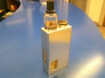
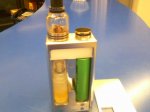
some box pictures of mine hope you like itView attachment 20841View attachment 20842View attachment 20843View attachment 20844View attachment 20845
Forgot to tell. Cnc hammond 1590g. Serieel. Mosfet switch. Mitec button Positiv straight on the keystone tab. And alao the source of the mosfet on the negatif. So no thick wires.
Very nice box Mau, I'm a little confused on the enclosure though, you say that's a hammond 1590G? Or is it a CNC version of the hammond? It's very nice either way, I'm just wondering if it's an actual hammond that went through some extreme modifications. I find it next to impossible to get the finishes that consistent and reflective due to the deposits of silicone Hammond uses in their alloys.
Mau
Member For 4 Years
Member For 4 Years
Member For 3 Years
Member For 2 Years
Member For 1 Year
New Member
Member For 5 Years
Sorrie its a cnc enclosure hammond g size 
Yes it is hard to get that finish With a standard hammond diecast aluminium The cnc enclosures are made of 6061 alu. That gives that shiny look
Verzonden vanaf mijn iPad met behulp van Tapatalk

Yes it is hard to get that finish With a standard hammond diecast aluminium The cnc enclosures are made of 6061 alu. That gives that shiny look
Verzonden vanaf mijn iPad met behulp van Tapatalk
That's really cool! Good work man! These ideas have never occurred to me thank goodness for other creative folks!Hey guys, thought I would see if anybody has some builds going on.
I have some pics of a Dimitri clone that I converted to a bottom feeder. It has nothing to do with mosfets, but hey just keeping the thread alive
View attachment 21683
View attachment 21684
View attachment 21685
VapeTechnologies
VapeTechnologies LLC Advanced Custom Boxes
VU Donator
Member For 4 Years
Member For 3 Years
Member For 2 Years
Unlisted Vendor
Not sure anyone is really hell bent on keeping the thread on topic lol... the FET questions have been answered in full detail as much as possible. Pretty sure this is our neighborhood now for general MOSFET builds or whatnot. Let's keep it alive, there's some great work in here. Here's some of my latest.. 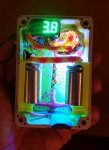

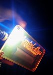
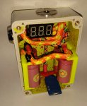


hey guys
so i have actually read through this entire thread and there is loads of information here, for that i must say thank you very much.
interested in getting all the right equipment the first time here and have some questions. first the difference between P and N Fets - it's simply the battery polarity?? I believe i will be purchasing this mosfet @wabah58 posted quite a bit ago in this thread... this is really a great mosfet as far as i can tell and the type N fet that correlates with the wiring diagram i believe i would like to follow.
Now as heat wrapping goes - why are you guys using heat shrink and what are you shrinking? is it necessary to do?
I intend to go with a bigger box from hammond i believe, a B probably so I can fit everything in there for my first box and not have to cram and whatnot - - - so wrapping up my 14 guage wire with electrical tape should be just fine right? it might not be the cleanest looking but it is the first mod i'll be hand crafting so...
Wow a lot of questions here.. Also last one for a bit - I see people talking about resistors wired in addition to mosfets... Why??
thanks guys i am still looking aorund for the answers to these questions myself.
Last edited:

