DIY FancyLights
Member For 4 Years
I'm not doing do good myself in trying to explain either today.
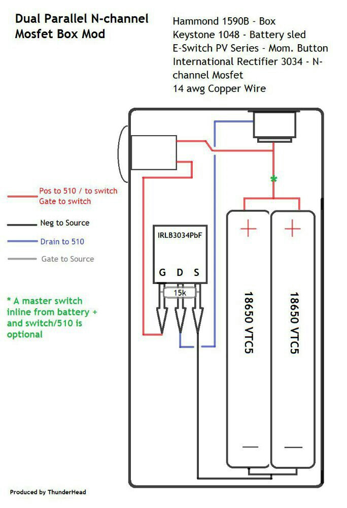
Thought I'd have ago at making one few weeks ago turned out ok I think anyway.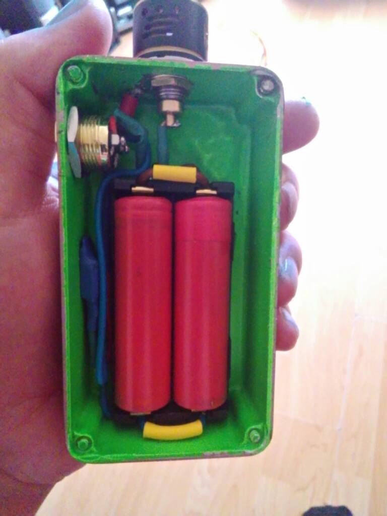 the wiring diagram I used.
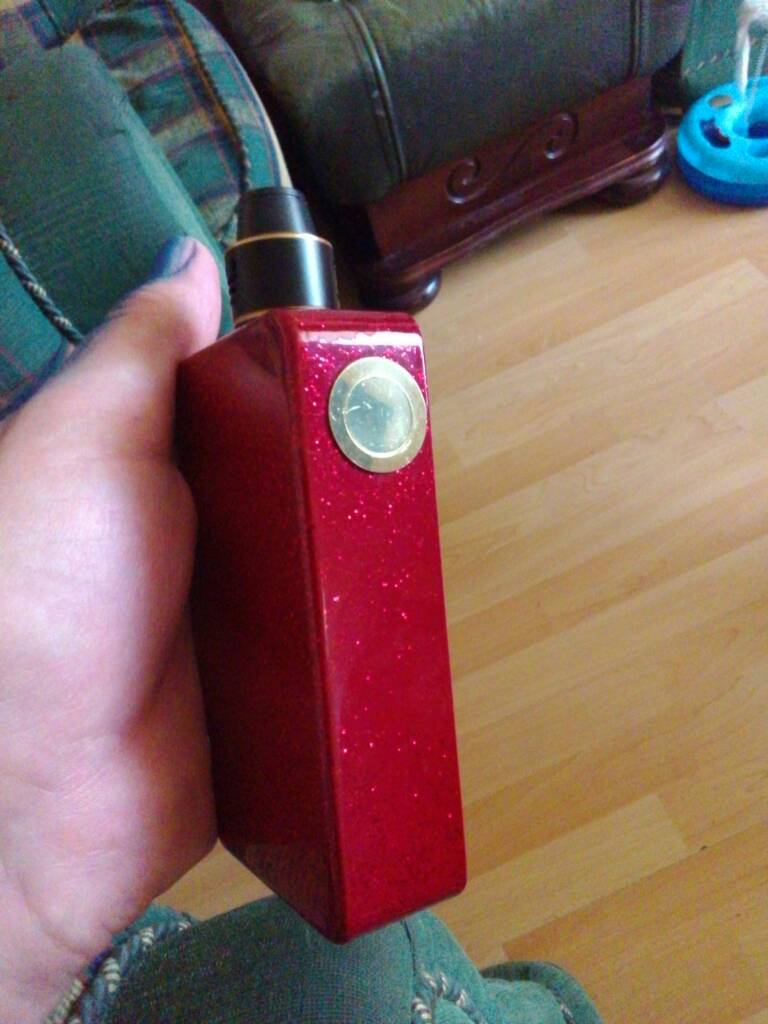
Sent from my P022 using Tapatalk
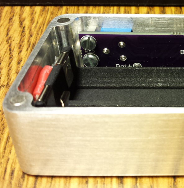
Ok guys finally finished the box now I just need to get a matches set of batteries cracked my lid trying to figure out the best way to get the magnets in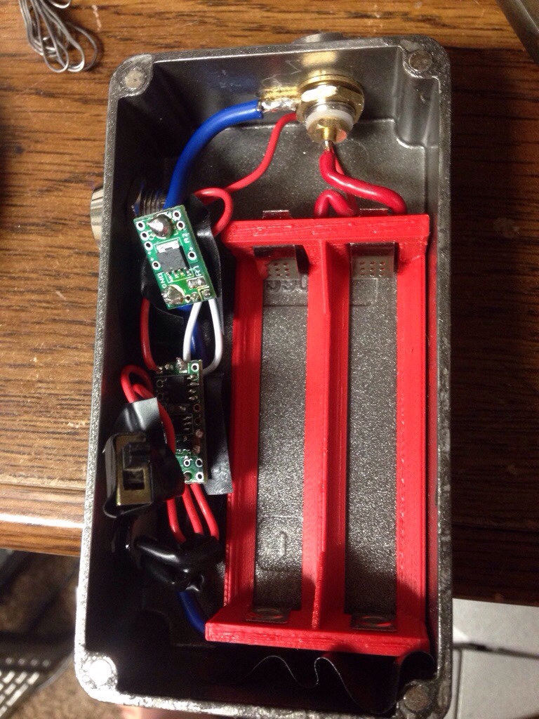
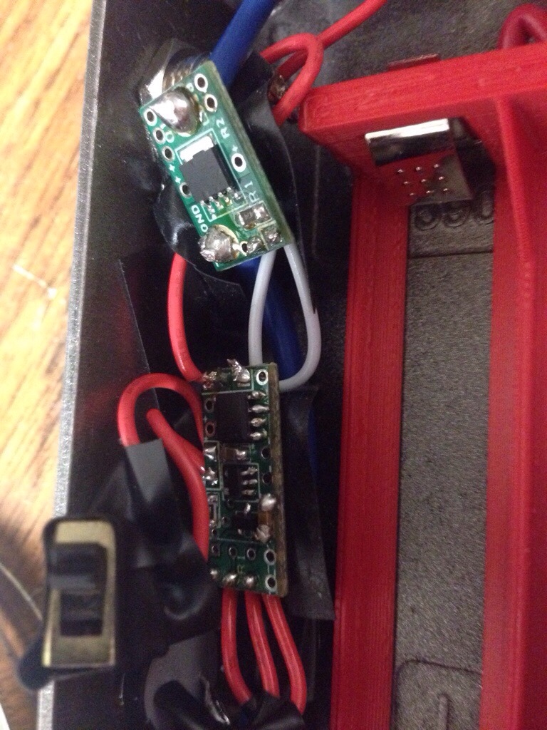
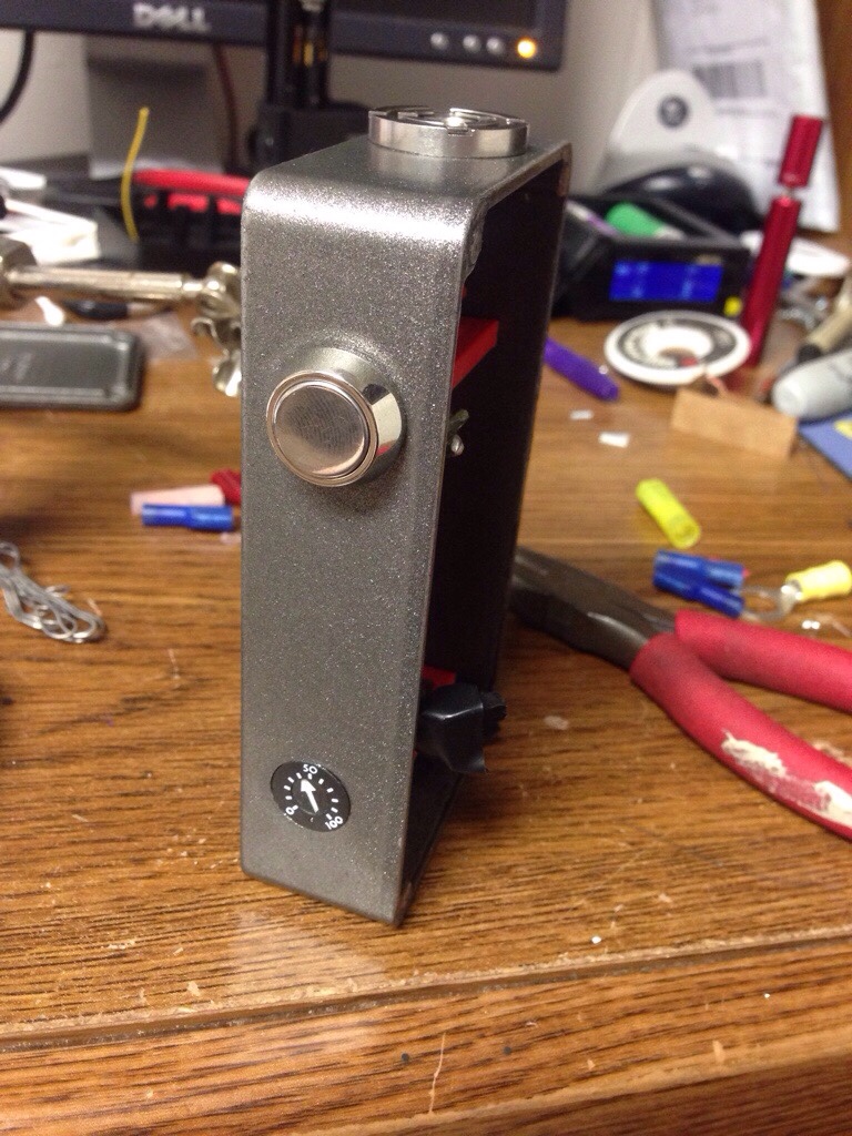
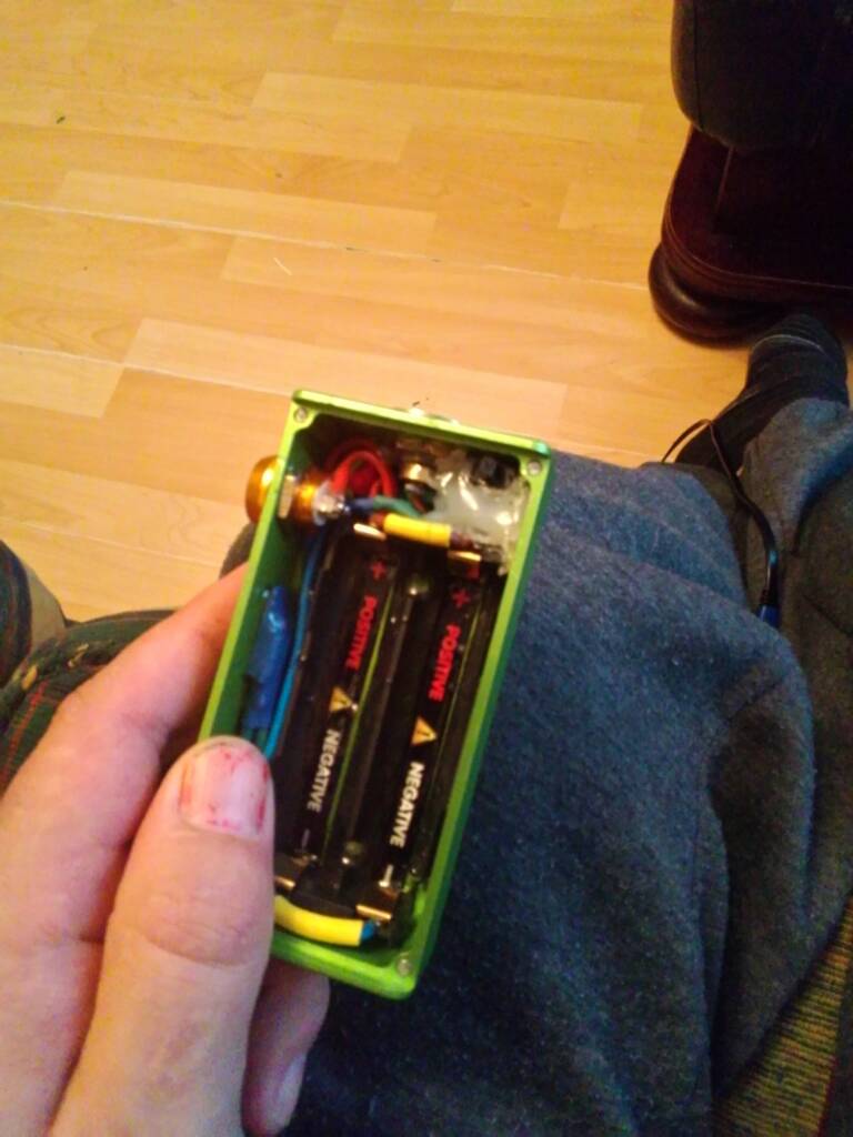
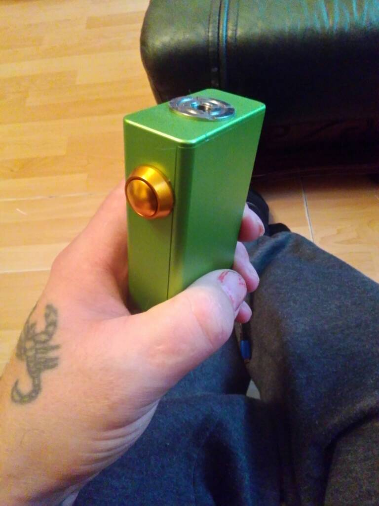


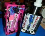
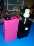
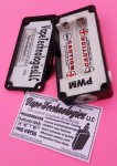
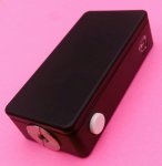
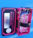
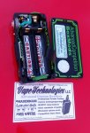

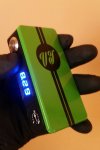
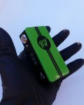
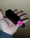

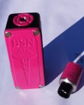


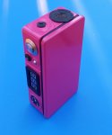
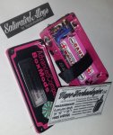
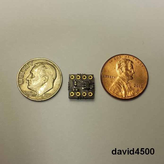
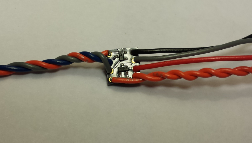
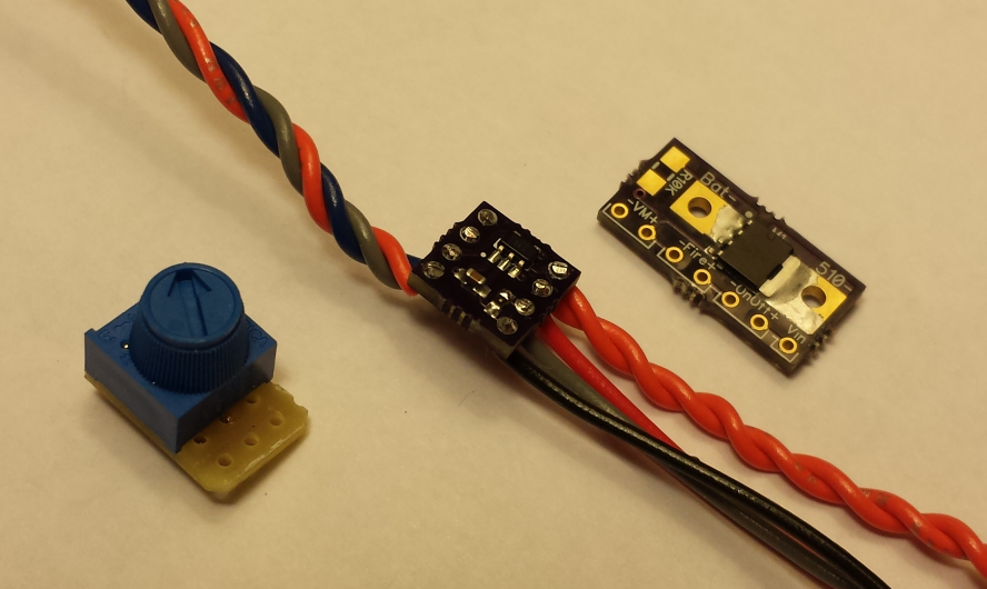
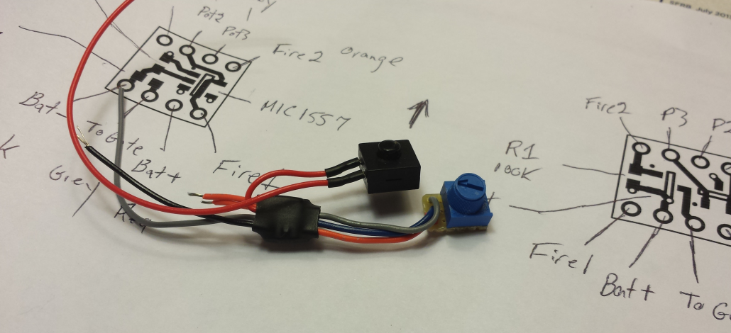
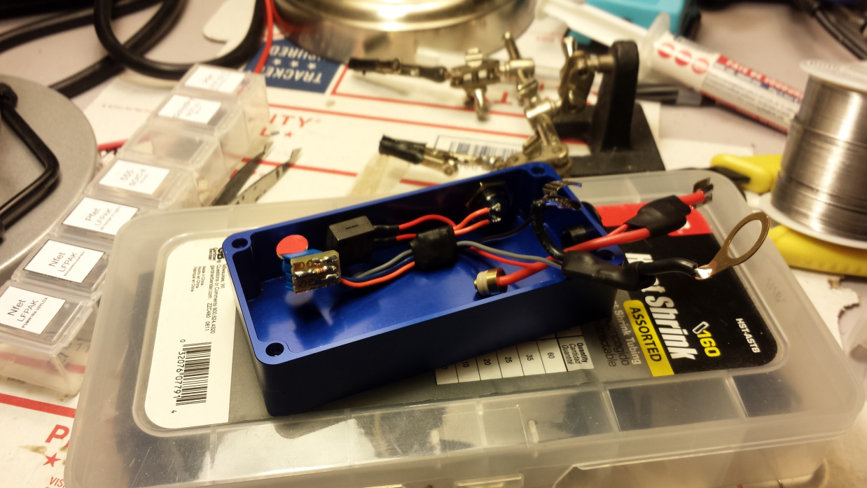
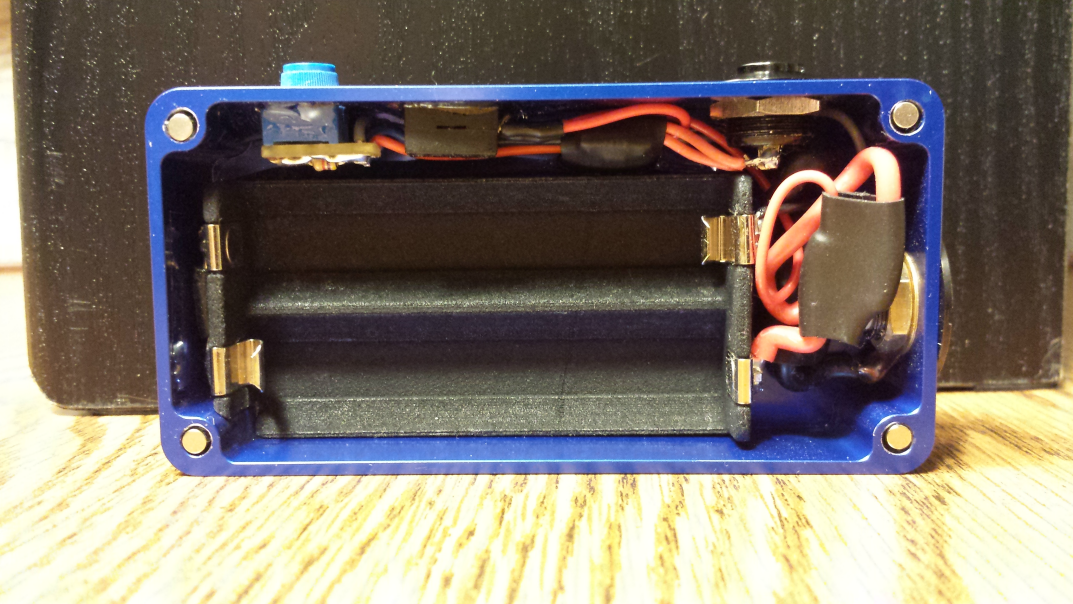
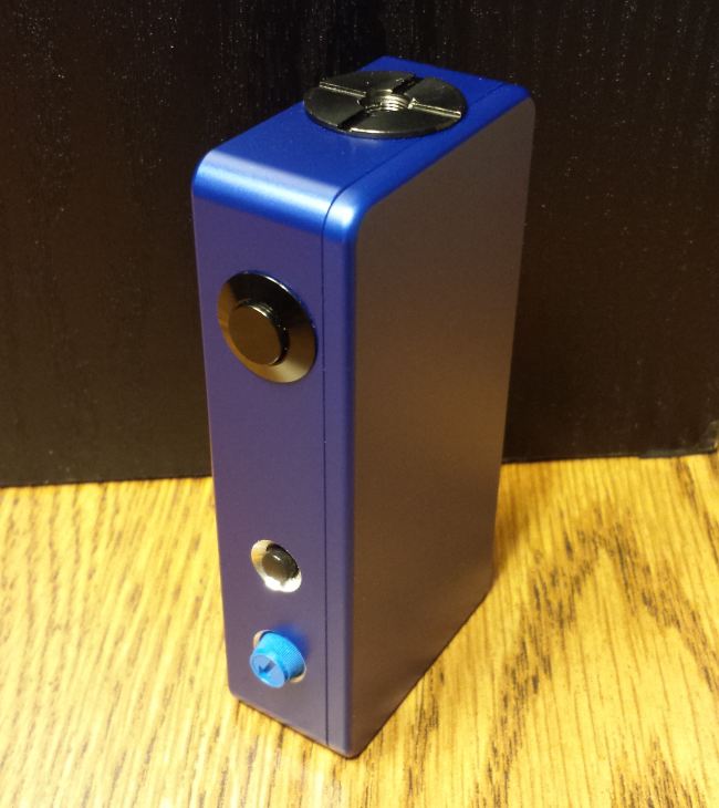
1590G with 800 mah battery show (fits 1600mah)


form factor is spot on.
heres one of a 1590A I did same 800 mah battery. forgot internal shots
[/QUOTE-would you happen to have diagram,I'm trying to build one myself,any help would be great. Thanks!
I'd really like to buy one of those pwms of you all soldered up,how much would u charge? Thanks and if not awesome work anyway!
$4.25 too much?
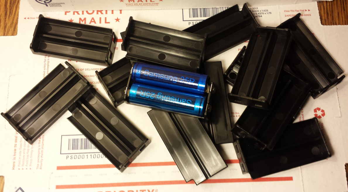
They are injection molded nylon 66 (zytel). I don't have them available yet. These are just the samples. Still need to do a production run.
"Long toim reada, foist toim colla!"
This thread is one of the greatest things to ever come from the internet. Ok, maybe that's overstating things a bit.I've been looking into building a Mod for over a year but never bit the bullet. I've been reading up on mods for a very long time and following this thread forever as well. I've finally decided to bite the bullet and can't wait to get started. I've been building DIY electronic gadgets for years now, so I went through a bunch of boxes of my electronics and have everything I need, several different MOSFET's, buttons, caps, you name it. I have an old IPV 3 that went capooey awhile back, so I figured I'll reuse the box and 510. Hopefully I can find some time this week to make a decent Sub-ohm VV LR HV mod based on all of the great information this thread contains. I've gotta say, the community on this board is top notch so I had to sign up. This is my first forum ever - I'm very anti social - that's how much all y'all rock.
Just wanted to say thanks for everyone's info, dedication, and helpfulness. Hope to be able to help contribute someday. Cheers!
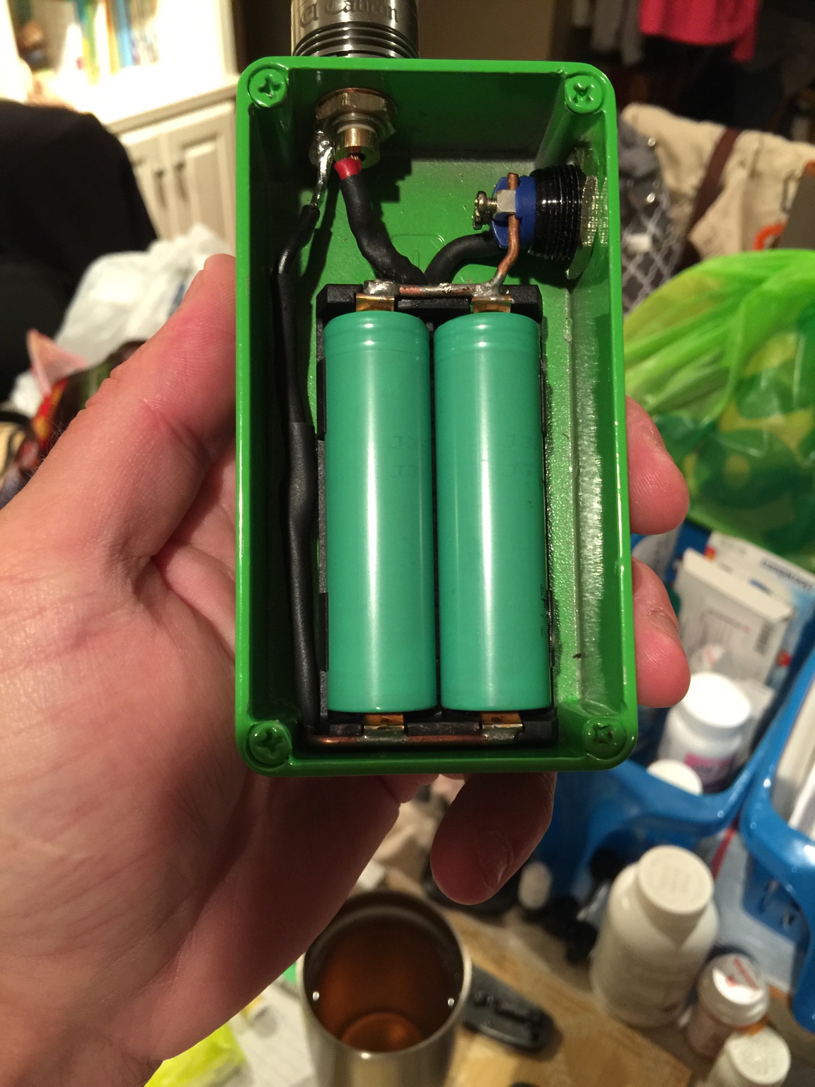
Sent from my iPhone using Tapatalk
With those contacts when the sled is sitting in box resting on the boss edge of enclosure, does the bottom contacts hit the bottom of box?
Thanks man!That looks 100 times better than that first set you posted man, good job on improving that first try!
Just out of curiosity, I see 99% of these box mods using MOSFETs. I was looking at my supplies and came across an SCR (thyristor) that I have, an HC106D. Started thinking that maybe I could stir things up and look into using an SCR since it seems like a great option if I want to include a bunch of newer ideas and safety features in my box mod, such as voltage protection/discharge, PWM, USB pass through charging, etc. Seems like an SCR would be the best choice for implementing such things, although I'm still VERY noob in electronics, so maybe not.
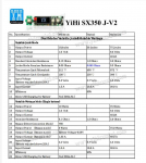
Anyhoo, did some googling to see if anyone else had done a mod using SCR's and I saw this Yihi SX350 chip for a box mod. I couldn't find any datasheets for it, but it has ALL of the gimmicks I was looking to put into my mod I'm about to start on. This thing is loaded with features! I'm betting their board is based on SCR IC. Does anyone know, or have knowledge of using an SCR for a box mod?
Although all of the kits, chips, boards, etc. that you folks have created or posted on this thread are very well done, I'm anal in the fact that I like to make EVERYTHING my own, from scratch, like starting a fire by rubbing sticks together rather than buying a match from a gas station. I also want to contribute some unique ideas to this community, so I thought if I took on this endeavor of doing an SCR based mod, I could help enlighten myself and perhaps bring something new to the table.
I know I should probably have posted this as a new thread, but I wanted to make sure I got the attention of you folks on this thread because I think you guys are top notch. If I end up going down this SCR mod road, I will start a new thread about this, asking questions, posting updates, etc.
Man,I talk a lot . . .
One last thing. Coletrain - yes, 1000 times better
I was looking at my supplies and came across an SCR (thyristor) that I have, an HC106D. Started thinking that maybe I could stir things up and look into using an SCR since it seems like a great option if I want to include a bunch of newer ideas and safety features in my box mod, such as voltage protection/discharge, PWM, USB pass through charging, etc. Seems like an SCR would be the best choice for implementing such things, although I'm still VERY noob in electronics, so maybe not.
ha ha ha, nice David. Crazy, the OP on your link sounds just like me, like some twin I never knew. That's oddly funny. Nice find. As for the cons that were posted on that thread, I've studied about ways to overcome those, such as the voltage drop, the "desire" for the SCR to want to stacy on, etc. But yes, even if I could overcome those things, it still is likely too complicated for me to do. If I did go the SCR route at this point, I would in fact buy theSC3X50j chip that Oggy pointed out. I was looking at that the other night, although the j chip doesn't support the USB passthrough for battery charging, so who knows which YIHI I'd go with.
Hey fellas. Check these out:


Over heated it when ya soldered it.I have my mosfet wired exactly like this diagram, but with a simple momentary 3a button. With or without the button installed, as soon as you install the battery - it starts firing. I'm very confused. Tried 2 different mosfets and same result. I'm using the 3034n from digikey just like a ton of other people use. The other difference from the diagram is that I'm using dual 18650's instead of a single. Any ideas why it might be auto firing? I did get it to work for about 5 pulses and then it went back to auto firing.
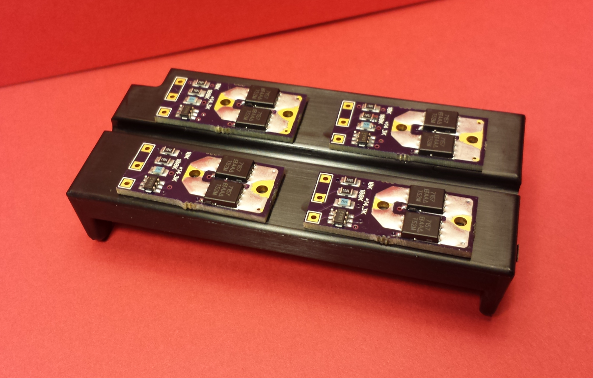
What does everyone think of the mosfet Si7157DP made by Vishay. It's a P fet, and surface mount, but what do you think about using one of these on a small PCB along with a surface mount resistor?
Potentiometer. That is likely a PWM (pulse width modulation) mod or possibly an OKR, OKL or Raptor. If you are making an unregulated mosfet mod, you cannot simply add a potentiometer and be able to adjust the output. Additional circuitry is required.
 https://postimage.org/index.php?lang=italian
 https://postimage.org/index.php?lang=italian
Hello,Builds in tight spaces was part of my incentive for making the microFET board to save space around the NFET while simplifying wiring.
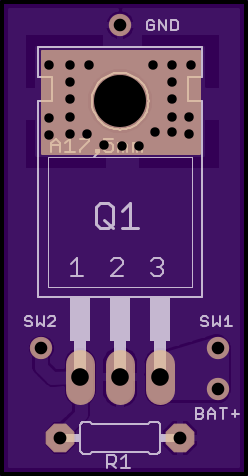
@Warhawk-AVG , Do you still have any of the mosfet boards? If so, I'd like to get 3 of them.I made a Vaping Underground MOSFET box mod board, if interested, preliminary design...I might end up having to make another via hole for another wire, otherwise you will have to make a "Y" + battery cable...
2 layer board of 0.62x1.19 inches (16x30mm). $3.70 for three.
Top:
Bottom:
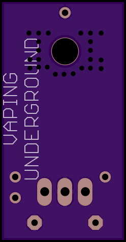
Any of the TO220 style N-Type MOSFETS, and any 1/4 watt resistor, cut the center leg, it's ground...that huge ground plane is now ground, solder any momentary switch on SW1 and SW2, solder the BAT+ to the center pin on the 510 connector, solder GND to the 510 outer housing....fire that puppy up
Here are some VERY good TO220 style MOSFETS
Thanks @david4500. Unfortunately, the link that needs to be copied and pasted to generate the order page doesn't work.

